Difference between revisions of "Part Verify Tutorial"
| Line 117: | Line 117: | ||
==='''Step 8'''=== | ==='''Step 8'''=== | ||
'''Now, another dimension will be placed'''. | '''Now, another dimension will be placed'''. | ||
| + | |||
| + | First, click the point at the center of the tube in the upper left corner to place the start of the dimension. Click the point at the starting edge of the point in the bottom right corner to place the end of the dimension. | ||
Revision as of 14:30, 10 July 2013
Contents
Introduction
This tutorial will step through the features and functions of the part verify plug-in.
The part verify plug-in is used to check part measurements to ensure the part design is correctly dimensioned.
Tutorial
Note
Before starting the tutorial, a part must be created. This tutorial will be using the part that was created in the XYZ Designer Tutorial. Please complete the XYZ Designer tutorial before proceeding.
Step 1
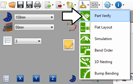
Once the part design is complete, go to the top of the window and click on the tools menu. Select the part verify option from the drop down menu to access the part verify plug-in.
Step 2
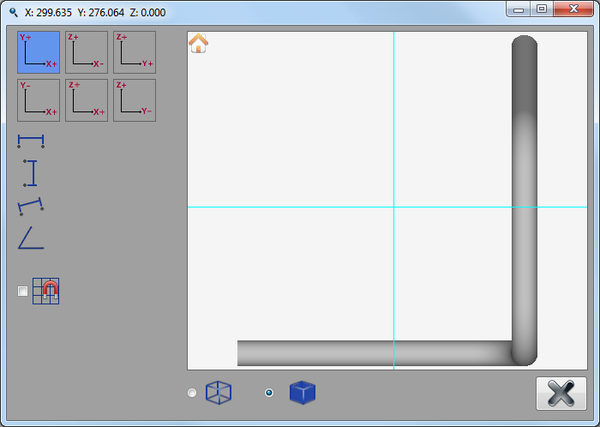
The part verify window will open.
Step 3
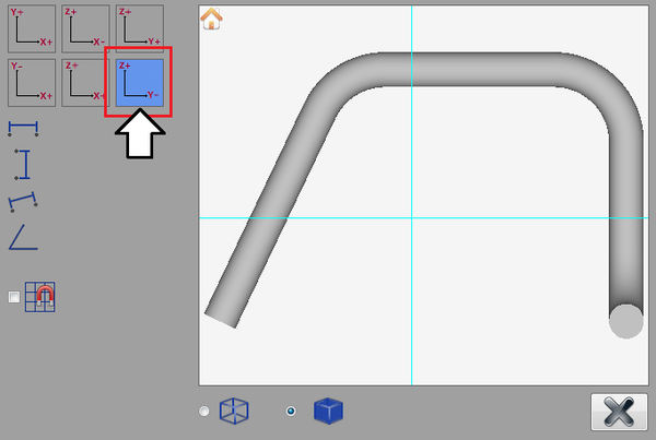
In the top left corner, there will be 6 different tiles that represent the view of the part along each of the X, Y, and Z axes. These are used to control which direction the part is viewed from.
Click the Z+ / Y- button.
Step 4
Now, the first dimension will be placed.
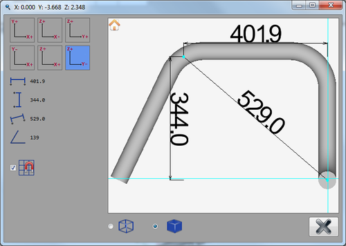
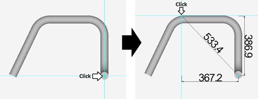
First, click the point approximately at the center of the tube in the bottom right corner. This will be the starting point of the dimension. After that point is clicked, move the cursor away and the dimensions will be generated as the cursor moves. Next, click the point on the outside edge of the straight length before the third bend to place the end of the dimension. See the image below.
Note: The dimension values displayed on the part may not be exactly the same as shown in the image below. This is because the chosen points are based solely on the accuracy of the mouse click when in 'free select mode'.
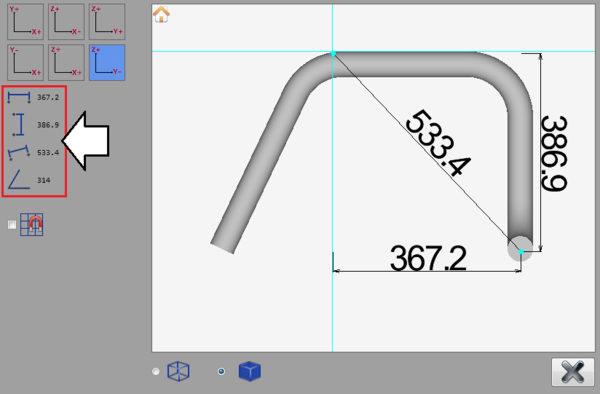
The part dimension values will be displayed on both the part model and on the panel on the left side of the window, as shown below. The dimension values on the left will list the horizontal, vertical, diagonal, and the angle measure of the diagonal dimension marker.
Step 5
Next, a new viewing direction will be chosen again.
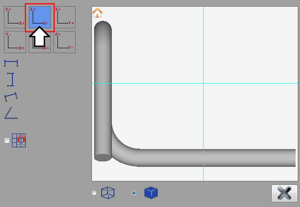
Click the Z+ / X- button.
Step 6
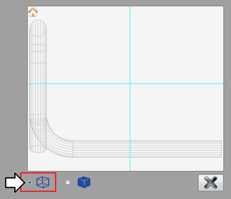
The part model can be viewed as a solid/shaded part or in wireframe. The options to control this are located just below the left corner of the part display frame.
Now, the part model will be switched to wireframe mode. To do this, click on the wireframe option as shown below.
Step 7
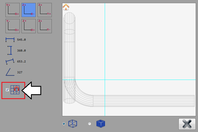
Next, instead of placing the dimension by choosing points freely, the snapping function will be activated. This will ensure the dimensions will snap to exact locations when placing the dimension start and end points. When this function is on, the only points that can be selected are the starting edge of the part, the start of a bend, the apex, the center of the bend, or the ending edge of the part.
Activate the snapping function by clicking the box next to the snapping icon, as shown below.
Step 8
Now, another dimension will be placed.
First, click the point at the center of the tube in the upper left corner to place the start of the dimension. Click the point at the starting edge of the point in the bottom right corner to place the end of the dimension.
