Difference between revisions of "Flat Layout Tutorial"
| (One intermediate revision by the same user not shown) | |||
| Line 28: | Line 28: | ||
==='''Note'''=== | ==='''Note'''=== | ||
| − | Before starting the tutorial, a part must be | + | Before starting the tutorial, a part must be completed. This tutorial will be using the part that was created in the '''[[Template Designer Tutorial]]'''. |
| Line 95: | Line 95: | ||
| − | Next, '''click on the blue | + | Next, '''click on the blue dot on the upper CLR label'''. After the dot is clicked, the label will be attached to the cursor. '''Move the label up and towards the left''' as demonstrated in the image below. Then '''click again''' to place the label in its new location. |
[[File:flattut10.png|850px]] | [[File:flattut10.png|850px]] | ||
Latest revision as of 08:46, 28 August 2013
Contents
Introduction
This tutorial will step through the features and functions of the flat layout plug-in.
The flat layout plug-in is used to place bend locations, rotations, angles, and/or CLR values on a 2D model of the unbent part. The 2D model with the labels and notes can be printed out.
Tutorial
Note
Before starting the tutorial, a part must be completed. This tutorial will be using the part that was created in the Template Designer Tutorial.
Step 1
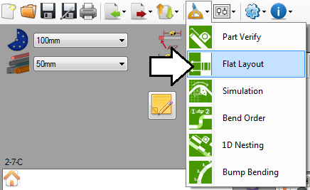
Once the part design is complete, go to the top of the window and click on the tools menu. Select the flat layout option from the drop down menu to access the part verify plug-in.
Step 2
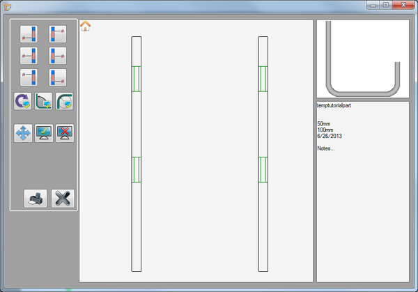
This will open the flat layout window. To the left, there will be the labeling options. In the middle, there will be two 2D models of the unbent part. And to the far right, there will be a 3D model of the complete part and an area with part information where notes can be added.
Step 3
Now the labels will be placed on the part.
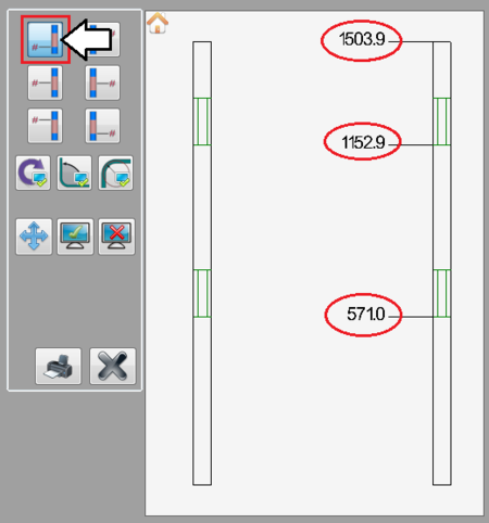
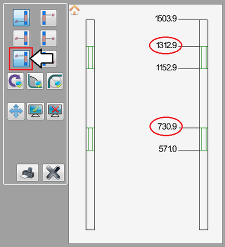
First, click the bend location button in the upper left corner (from start to beginning of bend). This will place a label at the start of each bend and at the end on the right part model. The label value will be the distance from the start of the part to each labeled location. See image below.
Step 4
Next, click the bend location button in the bottom left corner (from start to end of bend). This will place a label at the end of each bend on the right part model. The label value will be the distance from the start of the part to each labeled location. See image below.
Step 5
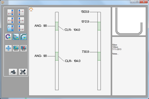
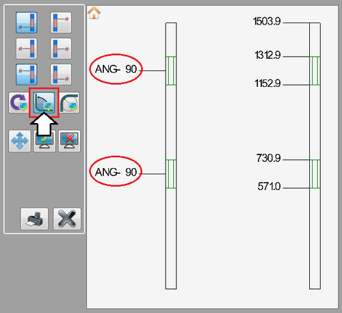
Now, click the angle button. This will place a label on each bend (sections marked off with green lines) on the left part model. The label values will be the angle that each of the bends will be bent to.
Step 6
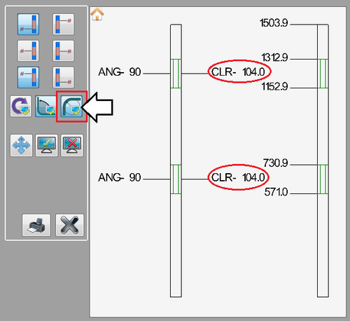
Now the last label will be placed. Click the CLR button. This will place a label on each bend that specifies the achieved CLR of the die that is used to make the bend.
Step 7
Now that all the labels are placed, their locations can be adjusted.
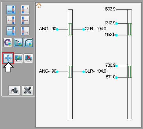
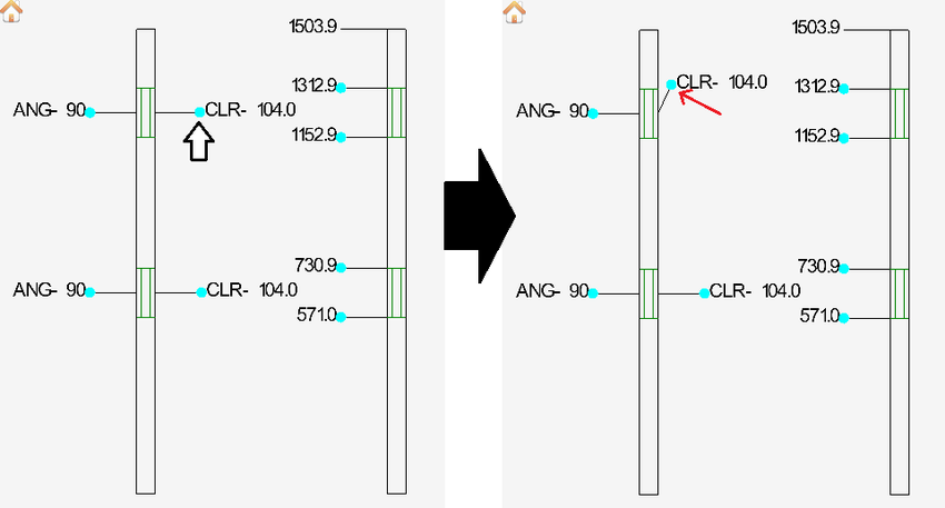
First, click the move button. Once this button is clicked, each label will have a light blue dot next to it, as shown in the image below.
Next, click on the blue dot on the upper CLR label. After the dot is clicked, the label will be attached to the cursor. Move the label up and towards the left as demonstrated in the image below. Then click again to place the label in its new location.
Step 8
Now a label will be removed/hidden.
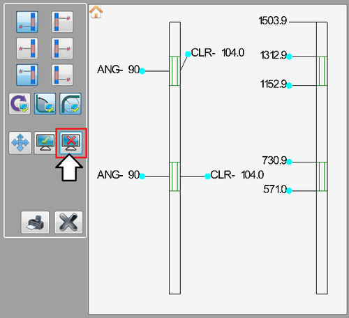
First, click the remove/hide button. Once this button is clicked, each label will have a light blue dot next to it, as shown in the image below.
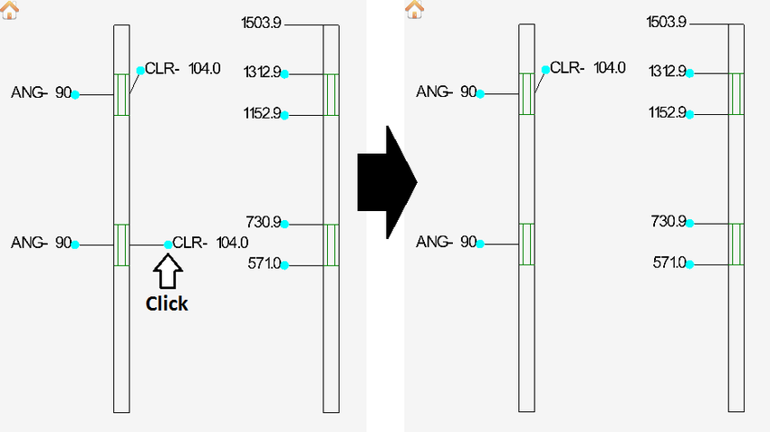
Next, click on the blue dot next to the lower CLR label. After the dot is clicked, the label will no longer be displayed.
Step 9
The part model can be zoomed in/out and moved.
Zoom in and out using the mouse scroll wheel or by pressing the plus [+] or minus [-] keys on the keyboard.
Move/pan the part around by clicking both mouse buttons and moving the cursor. The num pad keys can also be used to move the part. Press num 8 to move up, 2 to move down, 4 to move left, and 6 to move right.
Step 10
The tutorial is complete!
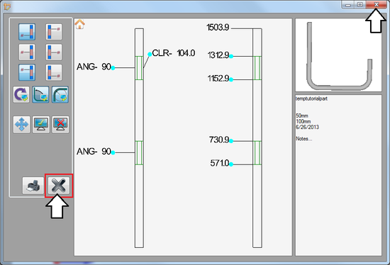
A print out of the labeled part along with the 3D part model and notes in the right panel can be printed using the print button. ![]()
Click the close button or the red X in the upper right corner to exit the flat layout plug-in window.
See the Flat Layout page for information on each individual function used in this tutorial.
