Difference between revisions of "Custom CLR Tutorial"
| (One intermediate revision by the same user not shown) | |||
| Line 22: | Line 22: | ||
==='''Note'''=== | ==='''Note'''=== | ||
| − | Before starting the tutorial, a part must be | + | Before starting the tutorial, a part must be completed. This tutorial will be using the part that was created in the '''[[Linear 2D Designer Tutorial]]'''. |
| Line 49: | Line 49: | ||
==='''Step 3'''=== | ==='''Step 3'''=== | ||
| − | '''In the third bend's CLR field, enter | + | '''In the third bend's CLR field, enter 200.''' |
[[File:custCLR04.png|800px]] | [[File:custCLR04.png|800px]] | ||
Latest revision as of 08:49, 28 August 2013
Contents
Introduction
This tutorial will step through the process of applying customized CLR values to a part's bends using the Custom CLR plug-in.The custom CLR plug-in allows CLR values to be given to individual bends instead of adding a die. Adding a custom CLR will basically act exactly like adding die, but it will not be stored in the die library.
Tutorial
Note
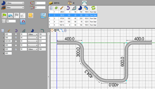
Before starting the tutorial, a part must be completed. This tutorial will be using the part that was created in the Linear 2D Designer Tutorial.
Step 1
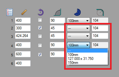
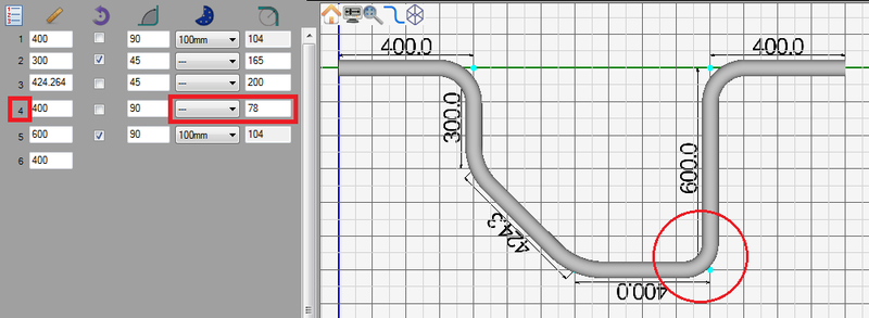
The second, third, and fourth bends will be given custom CLR values. First, in each die menu for these bends, click the drop down menu and select the "---" option. Doing so will allow values to be given in the CLR fields to the right of the menu.
Step 2
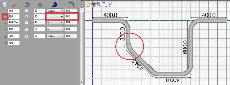
In the second bend's CLR field, enter 165. See image below.
Step 3
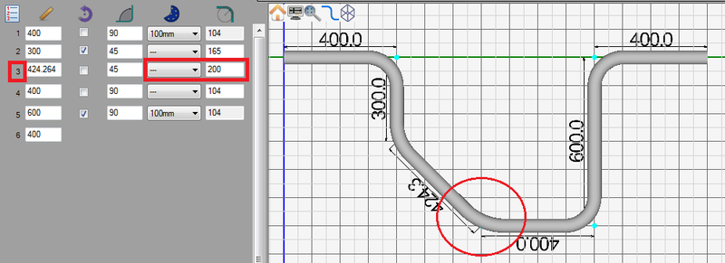
In the third bend's CLR field, enter 200.
Step 4
In the fourth bend's CLR field, enter 78.
Step 5
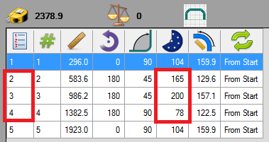
In the results table at the top of the window, each custom CLR value will be shown in the CLR column for bends 2, 3, and 4.
Step 6
The tutorial is complete!
For further information on this plug-in, see the Custom CLR plug-in page.
