Difference between revisions of "Import - Manual Definition"
| (4 intermediate revisions by the same user not shown) | |||
| Line 21: | Line 21: | ||
==Selecting Features== | ==Selecting Features== | ||
| − | Features must be selected to define a part. '''To select features''', first click the start button. [[File:startover.png]] Then, place the cursor over a feature. The feature will be highlighted in blue. Click on the feature to select it. Once selected, it will be highlighted in red. See image below. | + | Features must be selected to define a part. '''To select features''', first click the start button. [[File:startover.png]] Then, place the cursor over a feature. The feature will be highlighted in blue. Click on the feature to select it. Once selected, it will be highlighted in red. See image below. ''If necessary, an individual feature can be deselected by clicking on it again.'' |
[[File:mandef04.png|700px]] | [[File:mandef04.png|700px]] | ||
| Line 32: | Line 32: | ||
==Circles Only== | ==Circles Only== | ||
| − | While using this defining method, only circle features will be selected. To define a part using only circles, the following criteria must be met: | + | While using this defining method, '''only circle features''' will be selected. To define a part using only circles, the following criteria must be met: |
'''1.)''' Circles must be selected '''''in order''''', starting at the beginning of the part. See image below. | '''1.)''' Circles must be selected '''''in order''''', starting at the beginning of the part. See image below. | ||
| Line 51: | Line 51: | ||
'''To define a part using circles only''', click the '''start''' button and select all necessary circles on the part. Once the circles have been selected properly, click the '''finish''' button [[File:checkflag.png]] to generate the part. The part will be shown in the selected material and the bend chart will list each bend along with the CLR and die for each. The die chosen in the die menu will be automatically selected for each bend in the bend chart. | '''To define a part using circles only''', click the '''start''' button and select all necessary circles on the part. Once the circles have been selected properly, click the '''finish''' button [[File:checkflag.png]] to generate the part. The part will be shown in the selected material and the bend chart will list each bend along with the CLR and die for each. The die chosen in the die menu will be automatically selected for each bend in the bend chart. | ||
| − | [[File:mandef05.png| | + | [[File:mandef05.png|1000px]] |
| Line 77: | Line 77: | ||
'''To define a part using circles and lines''', click the '''start''' button and select each pair of circles and lines. Once everything is selected, click the '''finish''' button [[File:checkflag.png]] to generate the part. The part will be shown in the part display in the selected material. The bend chart will list each bend along with the CLR and die for each. The die chosen in the die menu will be automatically selected for each bend in the bend chart. | '''To define a part using circles and lines''', click the '''start''' button and select each pair of circles and lines. Once everything is selected, click the '''finish''' button [[File:checkflag.png]] to generate the part. The part will be shown in the part display in the selected material. The bend chart will list each bend along with the CLR and die for each. The die chosen in the die menu will be automatically selected for each bend in the bend chart. | ||
| − | [[File:mandef10.png| | + | [[File:mandef10.png|1000px]] |
| Line 91: | Line 91: | ||
| − | '''2.)''' The lines do not have to connect. Spaces are allowed between the selected lines | + | '''2.)''' The lines do not have to connect. Spaces are allowed between the selected lines. |
[[File:mandef12.png|700px]] | [[File:mandef12.png|700px]] | ||
| Line 98: | Line 98: | ||
'''To define a part using just lines''', click the '''start''' button and select each line. Once all the lines are selected, click the '''finish''' button [[File:checkflag.png]] to generate the part. The part will be shown in the part display using the selected material. The bend chart will list each bend along with the CLR and die for each. The die chosen in the die menu will be automatically selected for each bend. | '''To define a part using just lines''', click the '''start''' button and select each line. Once all the lines are selected, click the '''finish''' button [[File:checkflag.png]] to generate the part. The part will be shown in the part display using the selected material. The bend chart will list each bend along with the CLR and die for each. The die chosen in the die menu will be automatically selected for each bend. | ||
| − | [[File:mandef13.png| | + | [[File:mandef13.png|1000px]] |
| Line 128: | Line 128: | ||
'''To define a part using lines and arcs''', click the '''start''' button and select each line. Once all the lines are selected, click the '''finish''' button [[File:checkflag.png]] to generate the part. The finished part will be shown in the part display using the selected material. The bend chart will list each bend with the CLR and die for each. The die chosen for each bend will be automatically chosen based on the CLR of each selected bend arc. If the CLR doesn't match any of the dies in the die library, the die with the closest CLR will be selected. | '''To define a part using lines and arcs''', click the '''start''' button and select each line. Once all the lines are selected, click the '''finish''' button [[File:checkflag.png]] to generate the part. The finished part will be shown in the part display using the selected material. The bend chart will list each bend with the CLR and die for each. The die chosen for each bend will be automatically chosen based on the CLR of each selected bend arc. If the CLR doesn't match any of the dies in the die library, the die with the closest CLR will be selected. | ||
| − | [[File:mandef17.png| | + | [[File:mandef17.png|1000px]] |
| Line 162: | Line 162: | ||
| − | '''To define a part by selecting circles, lines, and arcs''', first click the '''start''' button and select each necessary circle, line and arc. Once all the features are selected, click the '''finish''' button [[File:checkflag.png]] to generate the part. The finished part will be shown in the selected material in the part display. The bend chart will list each bend with the CLR and die for each. | + | |
| + | '''To define a part by selecting circles, lines, and arcs''', first click the '''start''' button and select each necessary circle, line and arc. Once all the features are selected, click the '''finish''' button [[File:checkflag.png]] to generate the part. The finished part will be shown in the selected material in the part display. The bend chart will list each bend with the CLR and die for each. The die chosen for each bend will be automatically chosen based on the CLR of each selected bend arc. If the CLR doesn't match any of the dies in the die library, the die with the closest CLR will be selected. | ||
| + | |||
| + | [[File:mandef23.png|1000px]] | ||
Latest revision as of 12:24, 25 June 2013
Contents
Introduction
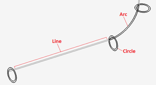
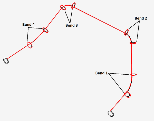
Parts can be imported by manually selecting certain features of the part. Parts are represented by lines, circles, and arcs - see image to the right. Depending on the part design and what kind of features are used to represent the part, some methods may be more appropriate than others.
Parts are defined by selecting...
1. Only circles (recommended)
2. Circles and Lines (recommended)
3. Only Lines
4. Arcs and Lines ...or
5. Arcs, Lines, and Circles
Selecting Features
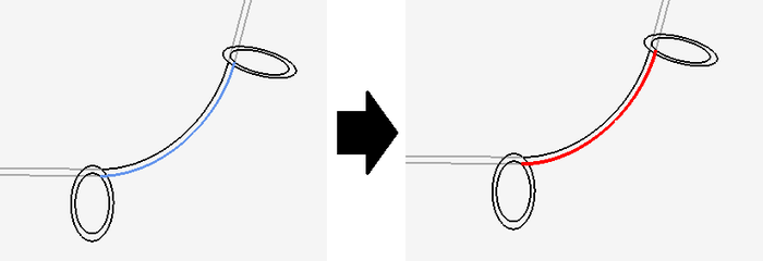
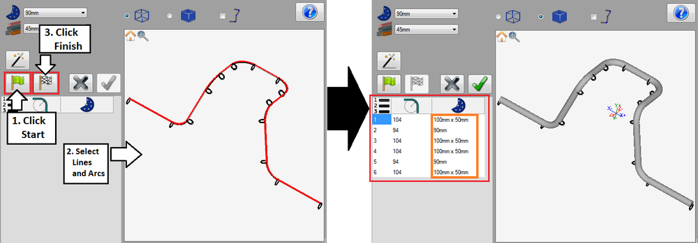
Features must be selected to define a part. To select features, first click the start button. ![]() Then, place the cursor over a feature. The feature will be highlighted in blue. Click on the feature to select it. Once selected, it will be highlighted in red. See image below. If necessary, an individual feature can be deselected by clicking on it again.
Then, place the cursor over a feature. The feature will be highlighted in blue. Click on the feature to select it. Once selected, it will be highlighted in red. See image below. If necessary, an individual feature can be deselected by clicking on it again.
Circles Only
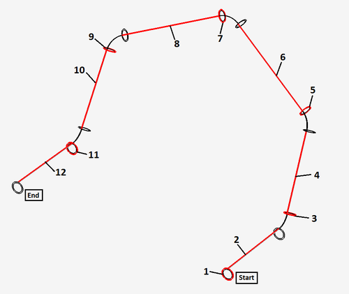
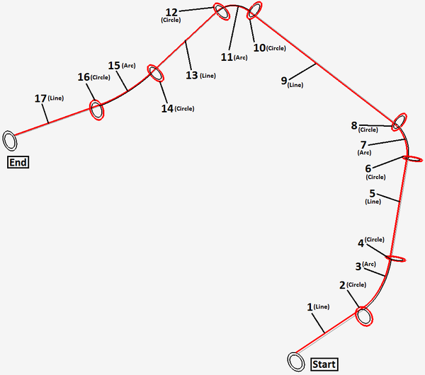
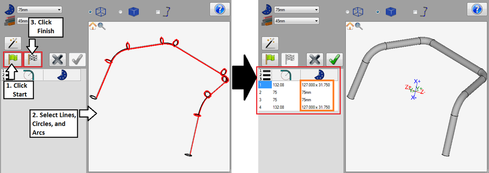
While using this defining method, only circle features will be selected. To define a part using only circles, the following criteria must be met:
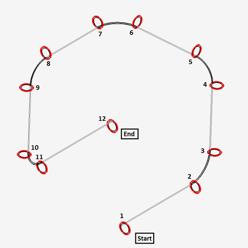
1.) Circles must be selected in order, starting at the beginning of the part. See image below.
2.) A circle is needed at the start and end of the part and at the start and end of each bend. See image below.
3.) Circles must be complete to be considered actual circles.
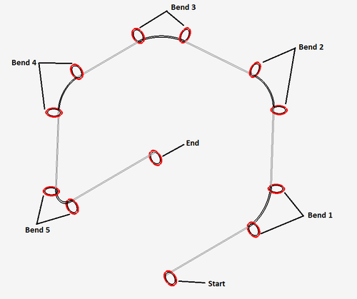
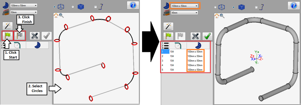
To define a part using circles only, click the start button and select all necessary circles on the part. Once the circles have been selected properly, click the finish button ![]() to generate the part. The part will be shown in the selected material and the bend chart will list each bend along with the CLR and die for each. The die chosen in the die menu will be automatically selected for each bend in the bend chart.
to generate the part. The part will be shown in the selected material and the bend chart will list each bend along with the CLR and die for each. The die chosen in the die menu will be automatically selected for each bend in the bend chart.
Circles and Lines
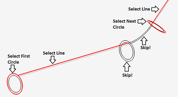
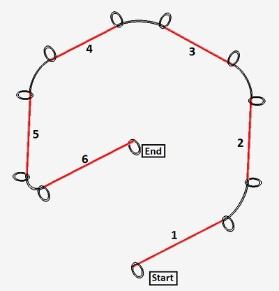
While using this defining method, only circles and lines will be selected. The lines selected do not represent the center line of the tube. The first circle will be the circle that defines the starting edge of the tube. Each single straight line will be paired with one circle that connects to the beginning of the line. For example, select the first circle then the line that extends from that circle. Skip the circle at the end of the selected line and anything between then continue with the following circle.
When defining parts using circles and lines, the following criteria must be met:
1.) Circles and lines must be selected in order starting with the first circle at the beginning of the part. See image below.
2.) Each circle and line pair must connect. There cannot be large gaps between the circle and line.
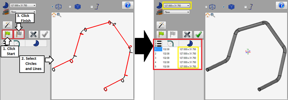
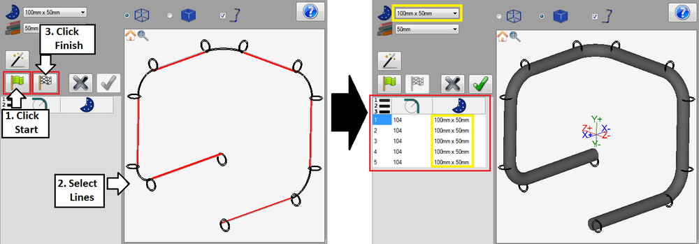
To define a part using circles and lines, click the start button and select each pair of circles and lines. Once everything is selected, click the finish button ![]() to generate the part. The part will be shown in the part display in the selected material. The bend chart will list each bend along with the CLR and die for each. The die chosen in the die menu will be automatically selected for each bend in the bend chart.
to generate the part. The part will be shown in the part display in the selected material. The bend chart will list each bend along with the CLR and die for each. The die chosen in the die menu will be automatically selected for each bend in the bend chart.
Lines Only
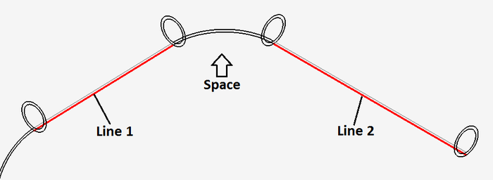
While using this defining method, only straight line features will be selected. The lines selected will represent the center line of the part. To successfully define a part using this method, the following criteria must be met:
1.) The lines must be selected in order starting from the beginning of the part.
2.) The lines do not have to connect. Spaces are allowed between the selected lines.
To define a part using just lines, click the start button and select each line. Once all the lines are selected, click the finish button ![]() to generate the part. The part will be shown in the part display using the selected material. The bend chart will list each bend along with the CLR and die for each. The die chosen in the die menu will be automatically selected for each bend.
to generate the part. The part will be shown in the part display using the selected material. The bend chart will list each bend along with the CLR and die for each. The die chosen in the die menu will be automatically selected for each bend.
Lines and Arcs
While using this defining method, only straight lines and arc features will be selected. The selected lines and arcs will represent the center line of the part.
To successfully define a part using this method, the following criteria must be met:
1.) The lines an arcs must be selected in order.
2.) The selected line and arc features must connect. There cannot be large gaps between the lines and arcs.
To define a part using lines and arcs, click the start button and select each line. Once all the lines are selected, click the finish button ![]() to generate the part. The finished part will be shown in the part display using the selected material. The bend chart will list each bend with the CLR and die for each. The die chosen for each bend will be automatically chosen based on the CLR of each selected bend arc. If the CLR doesn't match any of the dies in the die library, the die with the closest CLR will be selected.
to generate the part. The finished part will be shown in the part display using the selected material. The bend chart will list each bend with the CLR and die for each. The die chosen for each bend will be automatically chosen based on the CLR of each selected bend arc. If the CLR doesn't match any of the dies in the die library, the die with the closest CLR will be selected.
Lines, Arcs, and Circles
While defining parts using this method, line, circle, and arc features will be selected. The selected lines and arcs will not represent the center line of the part.
Note: This defining method is somewhat uncommon/used very seldom. In cases where this method could be used, it may be easier to just use the circles only or the circles and lines method.
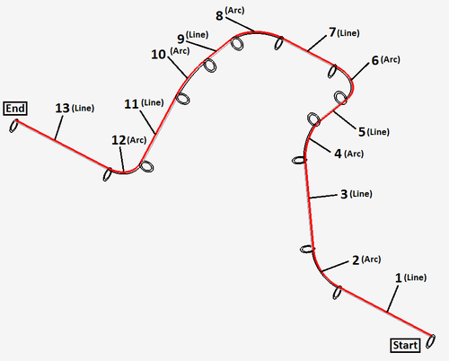
To successfully define a part by selecting lines, circles, and arcs, the following criteria must be met:
1.) The circles, lines, and arcs must be selected in order.
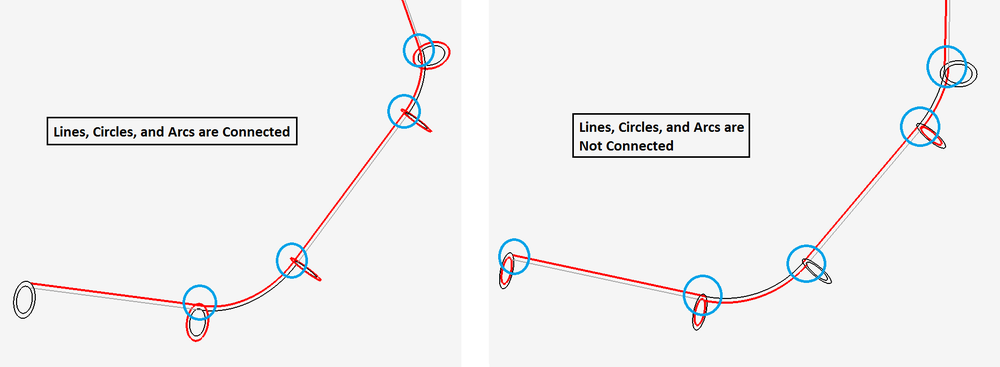
2.) Each circle, line, and arc must connect.
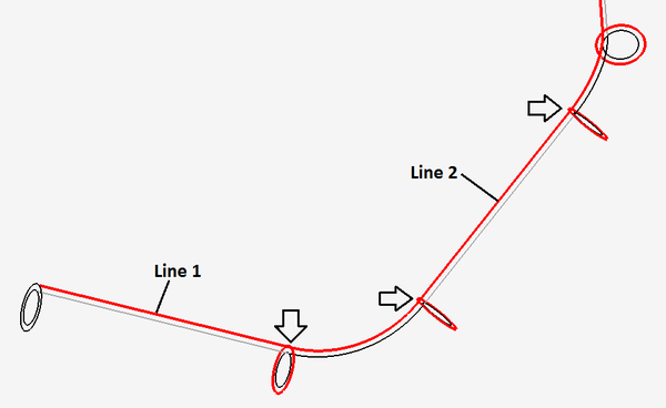
3.) Each straight line needs one circle at the start or end. Straight lines can have circles on both ends, but it is not required. For example, in the image below, line 1 has the circle at the end selected, but line 2 has both the start and end circles selected because it is in between two arcs.
4.) Each arc needs a circle on the start and end of each arc.
To define a part by selecting circles, lines, and arcs, first click the start button and select each necessary circle, line and arc. Once all the features are selected, click the finish button ![]() to generate the part. The finished part will be shown in the selected material in the part display. The bend chart will list each bend with the CLR and die for each. The die chosen for each bend will be automatically chosen based on the CLR of each selected bend arc. If the CLR doesn't match any of the dies in the die library, the die with the closest CLR will be selected.
to generate the part. The finished part will be shown in the selected material in the part display. The bend chart will list each bend with the CLR and die for each. The die chosen for each bend will be automatically chosen based on the CLR of each selected bend arc. If the CLR doesn't match any of the dies in the die library, the die with the closest CLR will be selected.
