Difference between revisions of "1D Nesting"
| Line 4: | Line 4: | ||
The 1D nesting plug-in will work independently from the designer interfaces. If a designer is closed or opened, 1D nesting will continue to run. As long as the software is still running, this plug-in will stay active. | The 1D nesting plug-in will work independently from the designer interfaces. If a designer is closed or opened, 1D nesting will continue to run. As long as the software is still running, this plug-in will stay active. | ||
| + | |||
| + | |||
Revision as of 14:35, 18 June 2013
Contents
Description
The 1D nesting plug-in helps determine how many parts of different lengths can be created from a single length of tube. The length of the main tube is given as well as the lengths of each individual part and how many are needed. After these values are supplied, a list of the parts that can be made out of each length of the main tube is generated. The amount of leftover tube is supplied as well.
The 1D nesting plug-in will work independently from the designer interfaces. If a designer is closed or opened, 1D nesting will continue to run. As long as the software is still running, this plug-in will stay active.
How To
Start Up
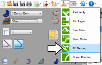
To access 1D Nesting, click the tools menu on the main tool bar. Click the 1D nesting option in the drop down menu, as shown below.
Note: When 1D nesting is opened, if the current part has been designed, it will be automatically added to the nesting project.
Attributes
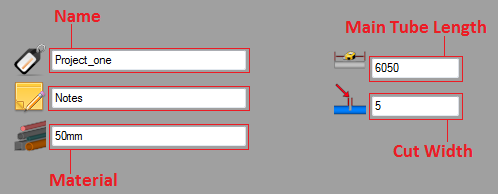
At the top of the window, there are fields that represent different aspects of the project. These will be included on the print out of the nesting project.
The name of the project is given after the name tag icon. When the project is saved, this will be the name of the nesting (.tsn) file.
Notes can be attached to the project next to the notes icon.
The material of the project is given after the material icon. This is the material of the main length of tube and all of the parts.
The length of the main tube is given after the length icon. This is how long the full length of tube is.
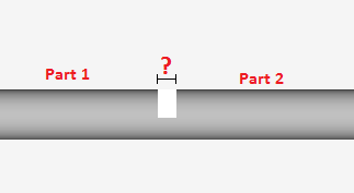
The cut/saw width is given after the cut width icon. This is the amount of material length that will be removed when making a single cut. See image below.
Add a Part
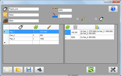
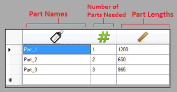
Each individual part is added to the chart on the left. There is a column for the part name, number of parts needed, and the length of the part. See image below.
Parts can be added to a nesting project a couple different ways.
1.) By sending a part over to the nesting project directly from the designer. First, design the part in any of the available designers then select the 1D nesting option ![]() from the tools menu
from the tools menu ![]() . If a nesting project is already open, the part will be added to the last row in the parts chart. If not, a new nesting project will be opened with just that part in the chart.
. If a nesting project is already open, the part will be added to the last row in the parts chart. If not, a new nesting project will be opened with just that part in the chart.
2.) By manually typing in a part name, number of parts needed, and the total length of the part. To do this, click in the name field in next empty row. Type in the name of the part. Click the tab key, or click in the next column to type in how many of this part is needed. Click the tab key, or click in the next column and enter the length of this part. Once these three values are supplied, a part has been successfully added to the nesting project.
Edit
To edit a part entry, click in the cell that will be changed. Once it's highlighted in blue, simply enter the new information.
Generate
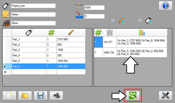
Once all of the parts are correctly added to the left chart, and the total length of the main tube and the cut length are entered, the nesting chart can be created.
Click the generate button ![]() to create the nesting chart.
to create the nesting chart.
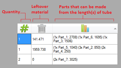
Each row will represent the parts that can be made from a single length of the main tube. This chart will consist of three columns. The first represents the quantity of main tube lengths required to create the listed parts in that row. The second represents the amount of tube that will be leftover after running the parts that are listed in the third column. The third lists all the parts that can be made with a single length of the main tube.
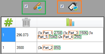
The third column can be customized using the length and name check boxes directly above the nesting chart. These control what information is included with each part or set of parts. At least one should be checked for the chart to be useful.
Check the length check box ![]() to include the lengths of the individual parts in the nesting chart.
to include the lengths of the individual parts in the nesting chart.
Check the name check box ![]() to include the names of the individual parts in the nesting chart.
to include the names of the individual parts in the nesting chart.
Notes:
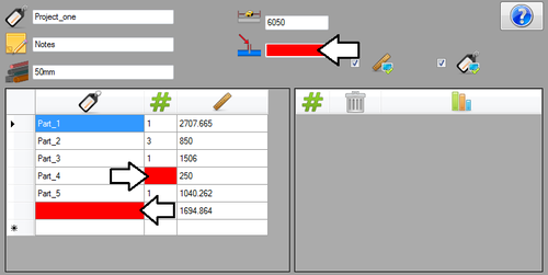
If any part or attribute information is missing when the generate button is clicked, the missing fields will be highlighted in red (see below) and the nesting chart will not be created. Fill in the highlighted fields and click the generate button again to create the nesting chart.
If the nesting chart cells are cut off or have information outside of the cell borders (see example below), adjust the cell size to ensure all information is visible. To do this, hover the cursor over the cell's edge. The cursor will become a vertical double arrow. Click, hold, and drag the cell to size.
Controls
In the bottom left corner of the 1D nesting window, there is a set of different buttons.
To start a new nesting project, click the new button. ![]() This will clear out all the fields. Take caution when using this button. If the current project hasn't already been saved, all entered information will be lost.
This will clear out all the fields. Take caution when using this button. If the current project hasn't already been saved, all entered information will be lost.
To open a nesting project file, click the open button. ![]() Choose a .tsn file from the Open file window and click open.
Choose a .tsn file from the Open file window and click open.
To save a new nesting project file, click the save button. ![]() In the save window, give the project a name and click save. If the project has already been saved to a file, use the save button to save changes.
In the save window, give the project a name and click save. If the project has already been saved to a file, use the save button to save changes.
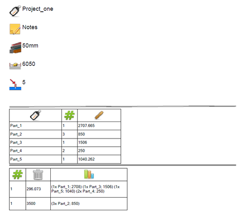
To print out a setup sheet of the nesting project, click the print button ![]() This will print out a sheet that includes all attribute information, the chart of the individual parts, and the nesting chart exactly as it is shown in the window. See image below for an example of what kind of information is included on a nesting print out.
This will print out a sheet that includes all attribute information, the chart of the individual parts, and the nesting chart exactly as it is shown in the window. See image below for an example of what kind of information is included on a nesting print out.
