Difference between revisions of "Break Tube Tutorial"
| Line 1: | Line 1: | ||
==Introduction== | ==Introduction== | ||
| − | This tutorial will step through the process of separating a part into different sections using the [[Break Tube]] plug-in. | + | [[File:breaktubetut13.png|right|470px]]This tutorial will step through the process of separating a part into different sections using the [[Break Tube]] plug-in. |
This plug-in is used to break parts into different sections when the total length of the part design exceeds the length of the material available. Breakpoints are placed on the part where each section will be broken off. Each section of the part will be shown in a chart and each can be sent to a part designer. | This plug-in is used to break parts into different sections when the total length of the part design exceeds the length of the material available. Breakpoints are placed on the part where each section will be broken off. Each section of the part will be shown in a chart and each can be sent to a part designer. | ||
| + | |||
| + | |||
| + | |||
| + | |||
| + | |||
| + | |||
| + | |||
| + | |||
| + | |||
| + | |||
| + | |||
| Line 41: | Line 52: | ||
==='''Step 3'''=== | ==='''Step 3'''=== | ||
| − | First, the '''length of the longest available tube''' will be supplied. '''Enter 2000 into the length field''' in the upper left corner. | + | First, the '''length of the longest available tube''' will be supplied. '''Enter 2000 into the length field''' in the upper left corner. This will limit how long each section of the part can be. |
Next, the '''minimum distance a breakpoint can be placed from a bend''' will be given. '''Enter 100 into the bend distance field''' (''To the right of the length field''). This means that the default breakpoint must be at least 100 mm from either side of each bend. | Next, the '''minimum distance a breakpoint can be placed from a bend''' will be given. '''Enter 100 into the bend distance field''' (''To the right of the length field''). This means that the default breakpoint must be at least 100 mm from either side of each bend. | ||
| Line 68: | Line 79: | ||
Next, custom breakpoint locations will be placed on the part. | Next, custom breakpoint locations will be placed on the part. | ||
| − | ''' | + | First, '''select the From Start option'''. Using this option, a breakpoint can be placed a specific distance from the beginning of the part. '''Enter 858 in the distance field'''. |
A purple point will be placed on the part 858 mm from the beginning of the part. This is '''''just a preview of the breakpoint''''' location. | A purple point will be placed on the part 858 mm from the beginning of the part. This is '''''just a preview of the breakpoint''''' location. | ||
| Line 75: | Line 86: | ||
| − | Now '''click the add button''' to place the breakpoint. Once the breakpoint is placed, it will turn green. The part sections in the chart will be adjusted. There will still be 2 parts, but the lengths will change due to the new breakpoint placement. | + | Now '''click the add button''' [[File:breaktubetut08.png]] to place the breakpoint. '''Once the breakpoint is placed, it will turn green'''. The part sections in the chart will be adjusted. There will still be 2 parts, but the lengths will change due to the new breakpoint placement. |
[[File:breaktubetut05.png|600px]] | [[File:breaktubetut05.png|600px]] | ||
| Line 86: | Line 97: | ||
==='''Step 6'''=== | ==='''Step 6'''=== | ||
| − | Next, a breakpoint will be placed using the From Bend option. | + | Next, a breakpoint will be placed using the '''From Bend''' option. |
'''Select the From Bend option'''. Using this option, a breakpoint can be placed a specified distance from the start of the length before a bend. | '''Select the From Bend option'''. Using this option, a breakpoint can be placed a specified distance from the start of the length before a bend. | ||
| Line 95: | Line 106: | ||
[[File:breaktubetut06.png|600px]] | [[File:breaktubetut06.png|600px]] | ||
| + | |||
| + | |||
| + | Now '''click the add button''' [[File:breaktubetut08.png]] to place the breakpoint. Once the breakpoint is placed, it will turn green. The part sections in the chart will be adjusted. There will now be three part sections in the chart since there are two breakpoints on the part now. | ||
| + | |||
| + | |||
| + | [[File:breaktubetut07.png|600px]] | ||
| + | |||
| Line 102: | Line 120: | ||
==='''Step 7'''=== | ==='''Step 7'''=== | ||
| + | Now the part has been broken into three sections. Each of these can be sent to a part designer from the chart at the bottom. In this step, the just first section of the part will be sent to a part designer. | ||
| + | |||
| + | First, '''select Part 2 in the chart by clicking on it'''. Once selected, the row will turn blue. Now, '''click the send button''' below the bottom right corner of the chart. A menu will open where a part designer interface will be chosen. '''Click on the XYZ part designer button''' to bring Part 2 into the XYZ interface. ('''''Note:''''' If XYZ isn't available, just select any of the other part designer buttons.) | ||
| + | |||
| + | [[File:breaktubetut11.png|1060px]] | ||
| + | |||
| + | |||
| + | |||
| + | |||
| + | |||
| + | |||
| + | |||
| + | ==='''Step 8'''=== | ||
Revision as of 08:54, 30 July 2013
Contents
Introduction
This tutorial will step through the process of separating a part into different sections using the Break Tube plug-in.
This plug-in is used to break parts into different sections when the total length of the part design exceeds the length of the material available. Breakpoints are placed on the part where each section will be broken off. Each section of the part will be shown in a chart and each can be sent to a part designer.
Tutorial
Note
Before starting the tutorial, a part must be created. This tutorial will be using the part that was created in the Linear 2D Designer Tutorial. Please complete the Linear 2D Designer tutorial before proceeding.
Step 1
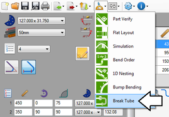
Once the part is complete, go up to the main menu bar, click the tools menu, and select the break tube option.
Step 2
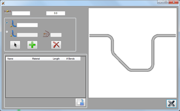
The break tube plug-in window will be opened.
On the right, there will be a 3D model of the part design. The full tube length and the minimum distance from bends will be supplied in the fields on the upper left. Below these fields there will be the tools used to place custom breakpoints. On the very bottom on the left, the part section chart will be generated.
Step 3
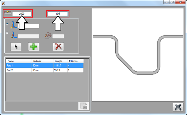
First, the length of the longest available tube will be supplied. Enter 2000 into the length field in the upper left corner. This will limit how long each section of the part can be.
Next, the minimum distance a breakpoint can be placed from a bend will be given. Enter 100 into the bend distance field (To the right of the length field). This means that the default breakpoint must be at least 100 mm from either side of each bend.
Step 4
Once the tube length and bend distance limit are supplied, the default breakpoint will be placed on the part. In the chart below, each section will be listed (Part 1 and Part 2).
Click on each section in the chart to see a preview of the section. When a part section is selected in the chart, the corresponding section on the part model will be highlighted in red. See image below.
Step 5
Next, custom breakpoint locations will be placed on the part.
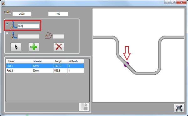
First, select the From Start option. Using this option, a breakpoint can be placed a specific distance from the beginning of the part. Enter 858 in the distance field.
A purple point will be placed on the part 858 mm from the beginning of the part. This is just a preview of the breakpoint location.
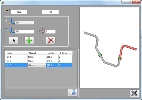
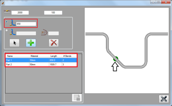
Now click the add button ![]() to place the breakpoint. Once the breakpoint is placed, it will turn green. The part sections in the chart will be adjusted. There will still be 2 parts, but the lengths will change due to the new breakpoint placement.
to place the breakpoint. Once the breakpoint is placed, it will turn green. The part sections in the chart will be adjusted. There will still be 2 parts, but the lengths will change due to the new breakpoint placement.
Step 6
Next, a breakpoint will be placed using the From Bend option.
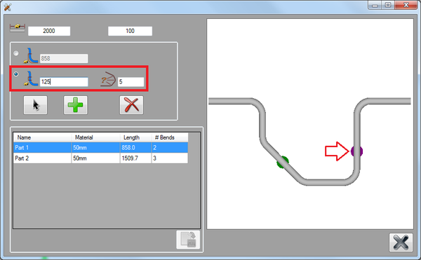
Select the From Bend option. Using this option, a breakpoint can be placed a specified distance from the start of the length before a bend.
Enter 5 in the bend field. Then enter 125 in the distance field.
A purple point (preview) will be placed 125 mm from the start of the length before bend number 5.
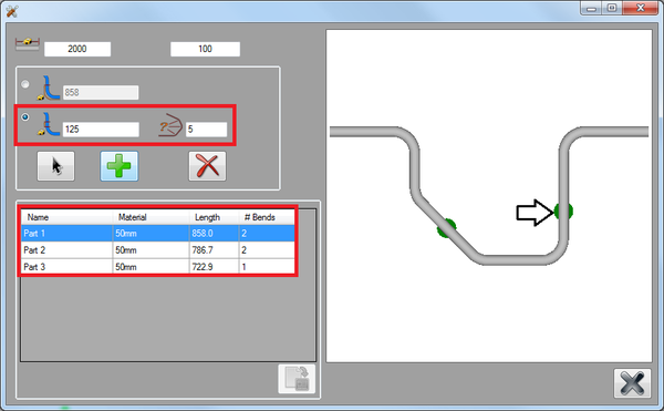
Now click the add button ![]() to place the breakpoint. Once the breakpoint is placed, it will turn green. The part sections in the chart will be adjusted. There will now be three part sections in the chart since there are two breakpoints on the part now.
to place the breakpoint. Once the breakpoint is placed, it will turn green. The part sections in the chart will be adjusted. There will now be three part sections in the chart since there are two breakpoints on the part now.
Step 7
Now the part has been broken into three sections. Each of these can be sent to a part designer from the chart at the bottom. In this step, the just first section of the part will be sent to a part designer.
First, select Part 2 in the chart by clicking on it. Once selected, the row will turn blue. Now, click the send button below the bottom right corner of the chart. A menu will open where a part designer interface will be chosen. Click on the XYZ part designer button to bring Part 2 into the XYZ interface. (Note: If XYZ isn't available, just select any of the other part designer buttons.)
