Difference between revisions of "Grapple Designer Quick Start"
| Line 122: | Line 122: | ||
'''To create a bend of 180°''' in the grapple designer, two 90° bends must be added with a small amount of straight tube in between them. | '''To create a bend of 180°''' in the grapple designer, two 90° bends must be added with a small amount of straight tube in between them. | ||
| − | '''''Note:''''' ''See the [[ | + | '''''Note:''''' ''See the [[Program Settings#General Tab|combine bends]] option on the program settings menu in the general tab section. This will allow two 90° bends to be combined into one 180° bend.'' |
[[File:grappart12.png]] | [[File:grappart12.png]] | ||
Latest revision as of 12:32, 19 August 2013
Contents
Add Bend
Adding a bend can be done two different ways:
1.) By double clicking on the center of the grapple tool (not a handle).
2.) By clicking the add bend button. ![]()
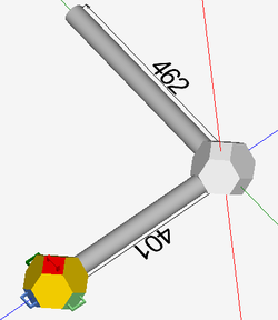
After a new bend has been added, the main axis will move to the new bend's location, as shown below.
Remove Bend
To remove the last bend added to a part, click the delete bend button. ![]()
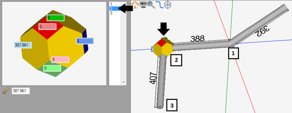
Select a Bend
Selecting a bend can done by clicking directly on the bend in the part display. When hovering the mouse over a bend, it will show a grey grapple shape around the bend, as shown to the right. Click on it to select. Bends can also be selected by clicking on the bend in the bend list.
Adjust Lengths
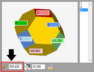
Before adjusting the length, select the bend on the end of the length. Adjusting a length on a part can be done using any of the following three methods:
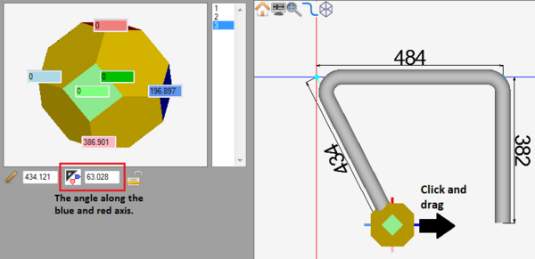
1.) By entering a value into the length field next to the ruler icon below the entry fields in the left panel.
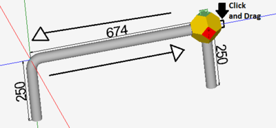
2.) By clicking and dragging a grapple tool handle in the direction of the straight tube.
3.) By clicking a grapple tool handle or by clicking and dragging a grapple tool handle that points in the direction of the straight tube and keying in the length value.
Adjust Angle
As the part is being designed, the angles of the bends will be generated automatically as needed. Using any of the three different part design methods can affect the angle:
1.) By clicking and dragging a grapple tool handle in the direction of the angle.
2.) By clicking on a grapple tool handle or by clicking and dragging the grapple tool handle that goes in the direction of angle and keying in a distance value. The value that is given will not be the angle value - it will be how far the tube will move in a certain distance to create the angle.
3.) By entering new values into any of the distance or angle entry fields in the left panel. The values in the angle fields represent the angle of the current part length along the specified axis, not the actual angle of the bend.
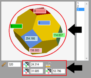
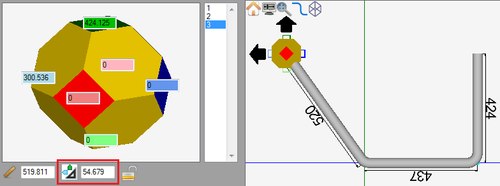
Once more than one angle is applied (Example: Pulled the green handle and then pulled light blue handle), the angle as well as the axis that the angle is along will be shown below the value fields in the left panel next to an axis icon. The colors of the small arrows on this icon correspond to the axes that the angle is along. The angle value can be also edited by entering a value directly into the given field.
If more than two angles are added, two more angle value fields will be generated. These will also have axis icons that will show which axes the angles are along. These can also be edited by directly entering values into the fields.
Individual bends' angles can be locked by clicking on and toggling the lock icon on or off. When a bend is locked, the angles of the bend will be locked in place if any attempts to change them are made. While locked, dragging the grapple tool around will only adjust the length of the straight after the bend.
Note: Be very careful when adjusting locked bends! Depending on the combination of angles on the bend, adjusting a locked bend can sometimes force the straight length to extend far past the intended length.
Adjust Rotation
As the part is being designed, the rotations of the bends will be generated automatically as needed. Using any of the three different part design methods can affect the rotation:
1.) By clicking and dragging a grapple handle.
2.) By clicking the grapple handle or by clicking and dragging the grapple handle and keying in the moving distance.
3.) By entering new values into any of the entry fields in the left panel.
Dimension Types
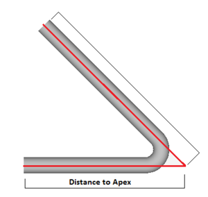
When creating parts in the grapple designer, all dimensions are measured from the apex of each bend. In this specific designer, there is no option to change this.
Start Over
To completely start over and delete all bend information, click the start over button. ![]()
Take caution when using this function. Once a part has been started over, its information cannot be retrieved again.
180° Bends
When creating parts in the grapple designer, 180° bends are handled a bit differently.
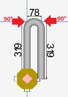
To create a bend of 180° in the grapple designer, two 90° bends must be added with a small amount of straight tube in between them.
Note: See the combine bends option on the program settings menu in the general tab section. This will allow two 90° bends to be combined into one 180° bend.


