Difference between revisions of "Break Tube"
| Line 26: | Line 26: | ||
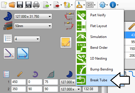
'''To access the break tube plug-in''', click on the tools menu on the main tool bar. Then select the break tube option from the drop down menu as shown below. | '''To access the break tube plug-in''', click on the tools menu on the main tool bar. Then select the break tube option from the drop down menu as shown below. | ||
| − | [[File:breaktube02.png | + | [[File:breaktube02.png]] |
Latest revision as of 13:18, 20 August 2013
Contents
Description
The break tube plug-in allows part designs to be broken up into different pieces. This is typically done when the total length of the part exceeds the length of the longest tube/stock available.
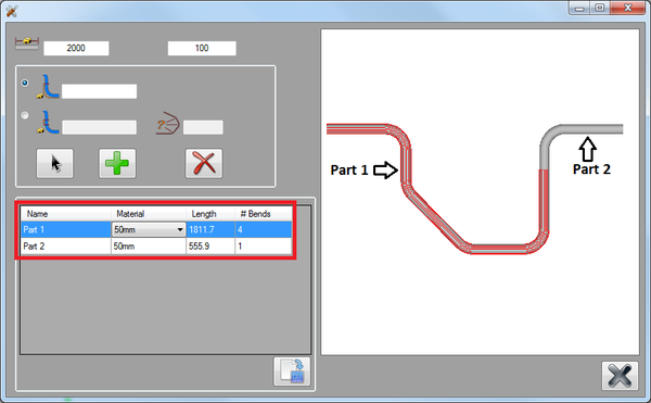
The longest tube length available and the required distance from each bend will be supplied. Breakpoints are placed along the part to define where the part will be separated. Then a chart of each individual part section with its material, length, and number of bends will be generated. From this chart, each part section can be exported to any of the part designers.
How To
Start Up
To access the break tube plug-in, click on the tools menu on the main tool bar. Then select the break tube option from the drop down menu as shown below.
Tube Length and Breakpoint Limits
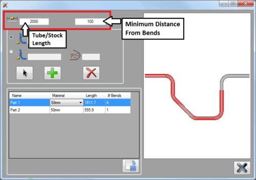
In the upper left corner, the total length of the longest tube available must be supplied in the left field. This length will determine how long each part section can be. In the field to the right, the shortest amount of material required on either side of a bend can be given.
Once the longest tube length and bend distance have been supplied, default breakpoints will automatically be placed on the part. The part sections will be generated in the chart below. Default breakpoint locations will be based off the tube length and required bend distance.
For example, in the image below, the longest tube length available is 2000 mm and each breakpoint must be at least 100 mm away from either side of a bend. The default breakpoints will be placed so each section length is under the supplied length (2000) and each breakpoint will be placed so they are at least 100 mm from the bends.
Add Breakpoints
Breakpoints will determine where each part section will be separated. They can be placed anywhere on the part except on bends. Keep in mind that breakpoint locations will not be limited by the bend distance value.
Breakpoints can be placed using three different methods:
1.) By specifying a distance from the start of the part to the location of the breakpoint.
2.) By specifying a distance from the beginning of the length before a bend to the location of the breakpoint.
3.) Using free select to click on the part model to define the breakpoint's location.
From Start
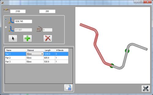
Breakpoints can be placed by defining a specific length from the beginning of the part. To do so, first select the From Start option. Enter the distance from the starting edge of the tube to define the location of the breakpoint. Once this value is entered, a purple point will be shown on the part to the right. This is a preview of where the breakpoint will be placed. To actually place the breakpoint, click the add button. The breakpoint will turn green once it is placed. The chart will adjust to accommodate the new breakpoint.
From Bend
Breakpoints can also be placed based off of a bend location. First, select the From Bend option. Enter the bend that the breakpoint will be placed before in the bend field, then Enter the distance from the beginning of the length before the bend in the distance field to define the breakpoint location. Once this value is entered, a purple point will be shown on the part model to the right. This is a preview of where the breakpoint will be placed. To actually place the breakpoint, click the add button. The breakpoint will turn green once it is placed. The chart will adjust to accommodate the new breakpoint.
Cursor Select
Breakpoints can also be placed by clicking on the part model. First, click the cursor select button. Then click directly on the part to choose the breakpoint location. The breakpoint preview will be shown in purple. Both the From Start and From Bend fields will be filled in with the current breakpoint's location. These values can be edited to adjust the location of the breakpoint if necessary. To place the breakpoint, click the add button.
Remove Breakpoints
To remove a breakpoint, first click the remove button. Then click directly on a breakpoint to remove it. The chart will be adjusted once the breakpoint is removed.
Part Section Chart
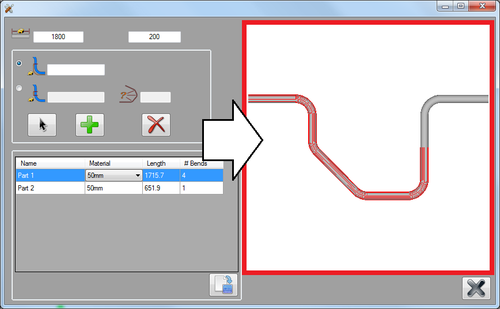
The chart will supply a list of each individual section of the part along with the material, length, and number of bends. Whenever a part is selected in this chart, it will be outlined in red on the part model to the right.
Change Part Name
To change a part section's name, click on the part in the chart to select it. Then just type in a new name for the part.
Change Material
To change a part section's material, click on the part in the chart to select it. Then click on the material drop down menu and select a material from the list. When the part section is sent to a part designer, this will be the material that is automatically selected in the material menu.
Send Part
From this chart, each bent section of the part can be sent to any of the available part designers. If any parts in the chart have zero bends, they cannot be sent to a part designer. Once the section is sent to another part designer, it will be treated as an individual part design.
To send a part to a designer, first select the part section in the chart by clicking on it. Then click the send button (bottom right corner of the chart). Another menu will open where a part designer can be chosen. Click on a part designer button. The part will then be brought into the selected interface. The break tube window will remain active, but will be minimized during the part transfer process.
Adjust View
The 3D part model to the right can be adjusted using any of the following methods:
To zoom in or out: Use the mouse scroll wheel. Scroll up to zoom out and scroll down to zoom in. (Note: This can be reversed using the invert zoom option. For more information on this option, see invert zoom on the program settings page in the General Tab section.) Or... Use the plus [+] or minus [-] keys on the keyboard. Press plus [+] to zoom in and press minus [-] to zoom out
To pan/move the part around the part display frame, click and hold down both mouse buttons and move the cursor around the frame. The part will follow the cursor. The num pad keys can also be used to move/nudge the part. Press Num 8 to move the part up, Num 2 to move the part down, Num 4 to move the part left, and Num 6 to move the part right.
To rotate the part, click and hold the right mouse button and move the cursor around.
