Difference between revisions of "Part Verify"
| Line 63: | Line 63: | ||
| − | '''To move the part around the part display frame''', click and hold down both mouse buttons and move the cursor around the frame. The part will follow the cursor. | + | '''To pan/move the part around the part display frame''', click and hold down both mouse buttons and move the cursor around the frame. The part will follow the cursor. |
Revision as of 10:19, 31 May 2013
Contents
Description
The part verify plug-in allows parts to be measured and dimensioned to ensure the accuracy of the part design.
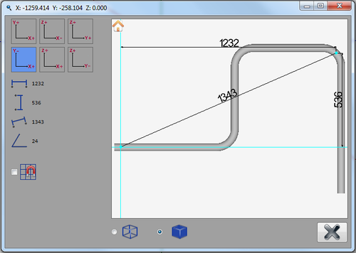
The part display frame includes the viewing controls in the top left, the dimension values just below that, and the snapping option at the bottom in the left panel. On the right, there is the part display frame with a model of the completed part that the dimensions can be applied to. Below the bottom left corner of the part display there are options to change the style of the part.
How To
Start Up
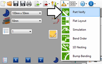
To access part verify, click on the tools menu on the main tool bar. Select the part verify option in the drop down menu, as shown below.
Controls and Options
Place a Dimension
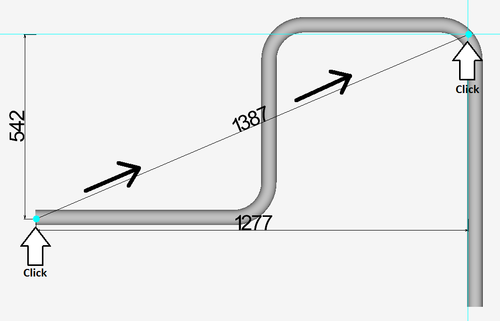
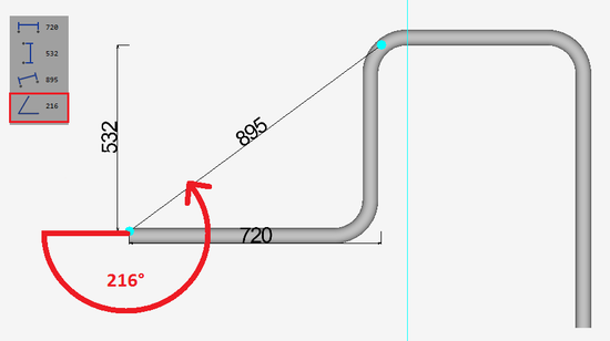
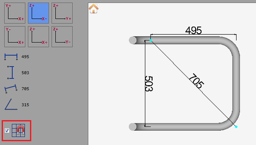
Each dimension will have three different measurements: horizontal, diagonal, and vertical. When placing a dimension, the first point chosen will be one of the corners and the second will be the opposite corner/diagonal from the first.To place a dimension, first click directly on the part where the dimension will start. Move the mouse and the dimensions will originate from the first point. Once the second point is chosen, the dimension will be set in place.
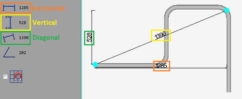
On the left panel, each dimension value (horizontal, vertical, and diagonal - below right) as well as the total angle of the diagonal dimension (See image below left) are shown.
Adjust View
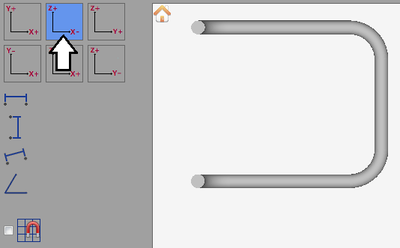
In the top left corner of the part verify window, there are 6 different axis tiles. These represent the different views of the part along the specified axes.
To change the view of the part, click on one of these tiles. Note: If any dimensions are on the part, they will be removed once the view is changed, but the dimension values will be remain in the left panel.
To zoom in or out, use the mouse scroll wheel. Scroll up to zoom out and scroll down to zoom in.
To pan/move the part around the part display frame, click and hold down both mouse buttons and move the cursor around the frame. The part will follow the cursor.
Part Display Options
To set the part display back to the default view, click the house icon ![]() in the top left corner of the part display frame.
in the top left corner of the part display frame.
To turn on the snapping function, click the check box next to the magnet/grid icon. When the snapping function is on, the dimensions will snap to the apex, center, or either edge of the bends depending on which one is closest to the cursor when choosing the dimension points.
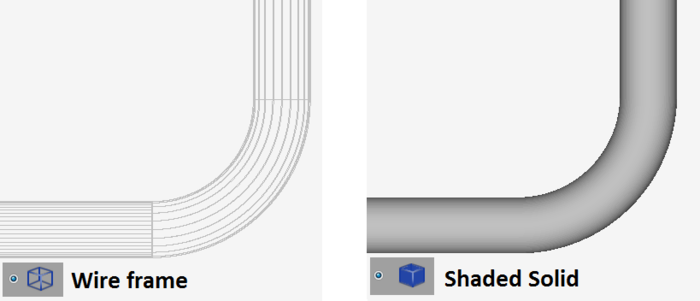
The 3D model of the part can be viewed in two different styles. To switch between wire frame or shaded solid model, either click the wire frame ![]() or the shaded solid
or the shaded solid ![]() model options.
model options.
