Export Template Tutorial
Contents
Introduction
This tutorial will step through the process of creating a custom export template using the Export Template plug-in.
The export template plug-in allows parts to be exported to a file with custom formatting that can include die, material, and part design information.
Tutorial
Note
This tutorial will be using the part that was created in the Linear 2D Designer Tutorial.
Step 1
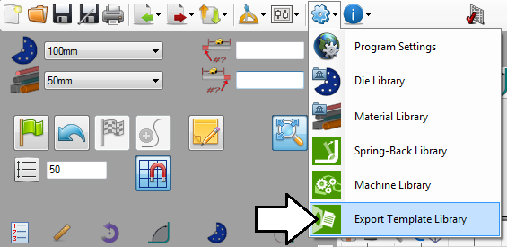
Go up to the top of the window and click on the Settings menu on the main menu bar. Select the Export Template option from the drop down menu as shown below.
Step 2
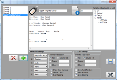
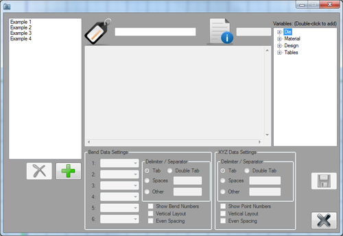
This will open the export template library. The list of templates is shown to the left. The area where the template will be designed is in the middle. On the far right, there will be a categorized list of variables. The variables will act as placeholders for the actual part information that will be included in the file.
Step 3
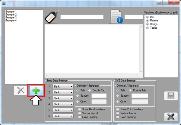
First, click the add button to start a new export template design.
Step 4
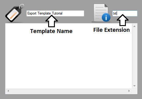
At the top, the name and the file extension for the template can be provided.
In the name field, enter "Export Template Tutorial" and in the file extension field, enter "txt".
Step 5
Now the template will be designed.
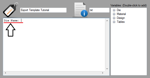
First, click in the text box to place the cursor. Type in "Die Name:" followed by one space.
Step 6
Next, the first variable will be placed.
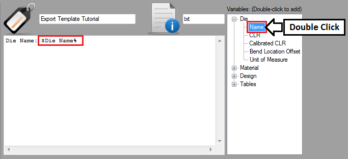
Variables are added to template designs from the list on the right. The variables are split into 4 categories: Die, Material, Design, and Tables. Each category can be expanded by clicking the small plus icons.
Expand the Die section and double click the Name variable to add it to the design. The variable ($Die Name%) should be placed after the text that was added in the previous step.
Step 7
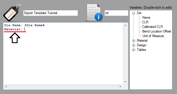
Next, click in the text box and hit the enter key on the keyboard to start a new line. Type in "Material:" followed by one space.
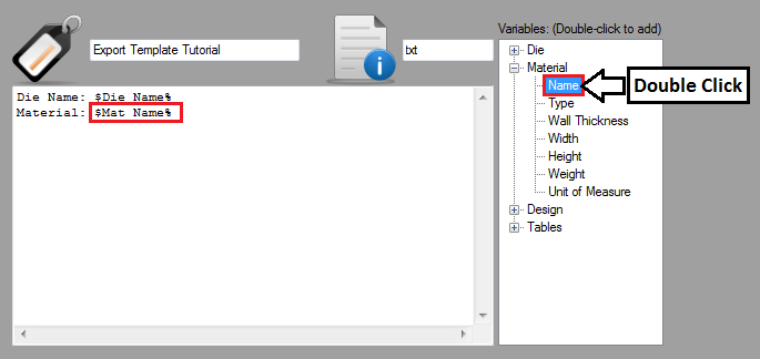
Now the material name variable will be placed. Expand the Material section in the variables list by clicking the plus icon next to it. Double click on the Name variable as shown below. The variable ($Mat Name%) should be placed right after "Material:".
Step 8
Next, click in the text box again. Hit the enter key twice to start a new line a couple rows down from the previous line of text.
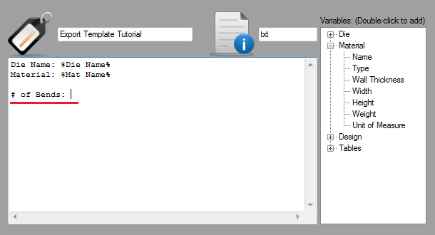
Type in "# of Bends:" followed by one space as shown below.
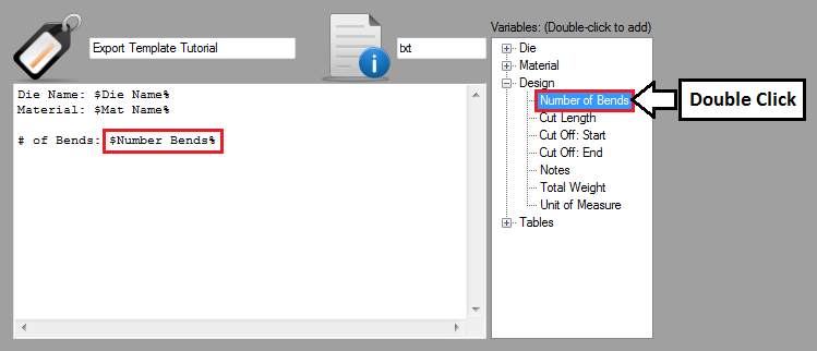
Now the bend number variable will be placed. Expand the Design section in the variables list by clicking the plus icon next to it. Double click on the Number of Bends variable as shown below. The variable ($Number Bends%) will be placed right after "# of Bends:".
Step 9
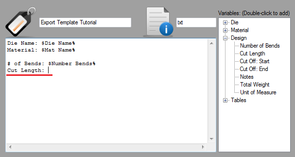
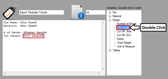
Click in the text box and hit the enter key. Then type in "Cut Length:" followed by one space.
Now the bend number variable will be placed. Double click on the Cut Length variable as shown below. The variable ($Cut Length%) will be placed right after "Cut Length:".
Step 10
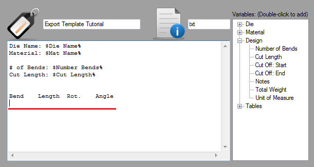
Click in the text box and hit the enter key three times. In this step, an LRA table will be added. First, the columns will be labeled.
Type in "Bend", hit the tab key, then type "Length", hit the tab key, type in "Rot.", hit the tab key, and then type in "Angle." After "Angle", hit the enter key.
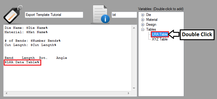
Now the LRA table variable will be added. In the variable list, expand the Tables section by clicking the plus icon next to it. Double Click on the LRA variable as shown below. The variable ($LRA Data Table%) will be placed below the text added previously.
Now the LRA table settings will be adjusted.
