Flat Layout
Contents
Description
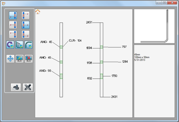
The flat layout plug-in allows an unbent model of the part to be labeled with the start, center, and end of bend lengths from either end of the tube, as well as the rotations, angles, and/or center line radius values. Individual labels can be hidden and moved, if necessary. The part image with labels, the 3D model, and the part information can be printed out.
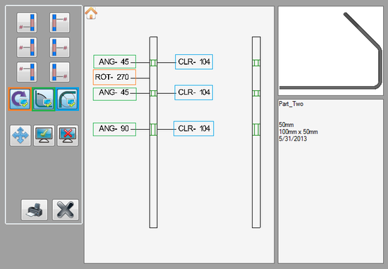
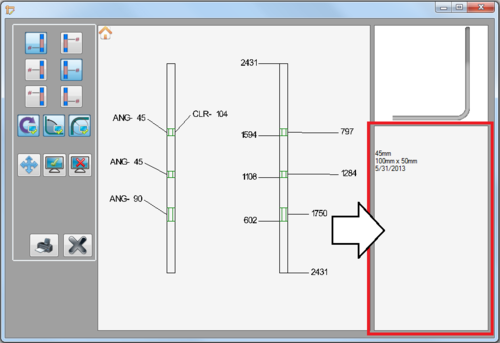
In the flat layout window, the label controls and the print button are in the left panel. The part display frame where the 2D, unbent model of the part is shown and where the labels will be applied is in the center of the window. There are two images of the same part shown - the left part will be labeled with the rotations, angles, and CLR while the right part will be labeled with the length values. Both part models have the start of the part at the bottom and the end at the top. In the right panel, a small 3D model of the bent part is shown. Below the model there will be part information such as the part's name, die, material, and creation date. The text displayed here can also be edited.
How To
Start Up
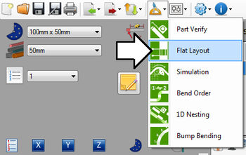
To access flat layout, click on the tools menu on the main tool bar. Click the flat layout option in the drop down menu, as shown below.
Controls and Options
Adding Labels
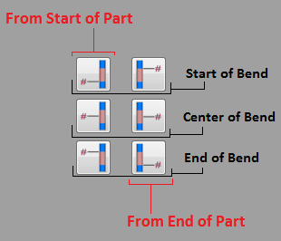
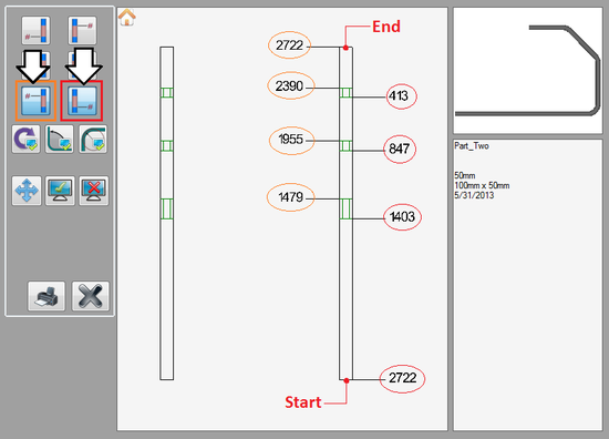
In the left panel, the first 6 buttons control the length labels. All these labels will be placed on the part model on the right. The 3 buttons on the left will place the distance/length measurements from the start of the part and the 3 on the right will place the length measurements from the end of the part. See image to the right.To place a length label, click on any of the length label buttons. Once a button is clicked, clicking it again will turn off all length labels that the button controls. See image below for an example.
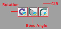
To place a rotation, angle, or CLR label, click on any of these buttons. Once a button is clicked, clicking it again will turn off all the labels that the button controls. See image below for an example.
Moving Labels
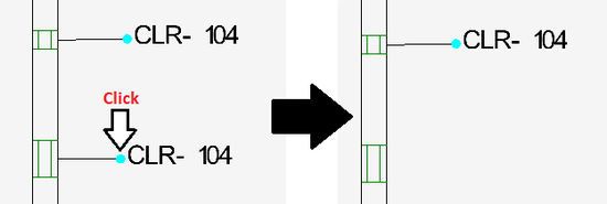
To move a label, first click the move button. ![]() Once this button clicked each label will have a light blue point. Click on a point to grab a label and move the cursor to a new location. Click again to place the label.
Once this button clicked each label will have a light blue point. Click on a point to grab a label and move the cursor to a new location. Click again to place the label.
Remove Labels
Individual labels can be removed. To remove a label, first click the hide button. ![]() Once this button is clicked, each label will have a light blue point. Click on a label's point to remove it.
Once this button is clicked, each label will have a light blue point. Click on a label's point to remove it.
Show All
Once labels are removed, they can all be brought back using the show all button. ![]()
Adjust View
The part display view can be changed using mouse controls and the home icon.
To set the view back to the default home view, click the home icon ![]() in the upper left corner of the part display.
in the upper left corner of the part display.
To zoom in and out, use the mouse scroll wheel. Scroll up to zoom out and scroll down to zoom in. (Note: This can be reversed using the invert zoom option. For more information on this option, see invert zoom on the Global Settings page in the General Tab section.)
To pan/move the part around the display frame, click and hold both mouse buttons and move the cursor around the frame. The part will follow the cursor.
3D Part Display
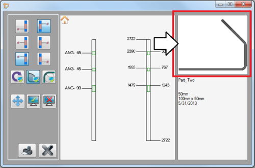
In the upper right corner of the flat layout window, there is a small 3D model of the complete, bent part. The view of this model can be changed.To zoom in or out, first click in the 3D part frame. Use the mouse scroll wheel to zoom in and out. Scroll up to zoom out and scroll down to zoom in. (Note: This can be reversed using the invert zoom option. For more information on this option, see invert zoom on the Global Settings page in the General Tab section.)
To rotate the part, first click in the 3D part frame. Click and hold down the right mouse button and move the cursor around.
To pan/move the part around the frame, first click in the 3D part frame. Click and hold both mouse buttons and move the cursor around the frame. The part will follow the cursor.
Part Information/Notes
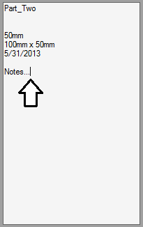
Below the 3D part display, in the bottom right corner, part information such as the part name, material, die, creation date, and notes will be generated.The text displayed here can be edited. To edit, click in the text area to place the cursor. Delete or add text as needed.
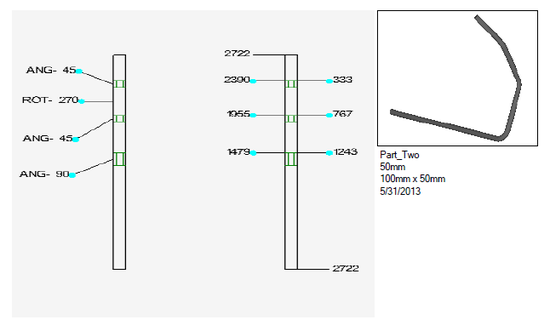
The part models, labels, 3D part, and the part information can be printed out. All label adjustments, the zoom extent, and part movement will be maintained in the printout. See image below for an example of what a flat layout printout can look like.
