1D Nesting Tutorial
Introduction
This tutorial will step through the functions of the 1D Nesting plug-in and the process of creating an example project.
The 1D nesting plug-in is used to determine how many different parts of varying lengths can be created and cut from a single length of tubing. The amount of leftover material will also be given.
Tutorial
Note
Before starting the tutorial, a part must be created. This tutorial will be using the part that was created in the Linear 2D Designer Tutorial. Please complete the Linear 2D Designer tutorial before proceeding.
Step 1
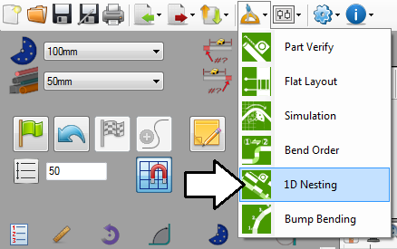
Once the part is finished, go up to the top of the window and click the tools menu. Select the 1D nesting option from the drop down menu as shown below.
Step 2
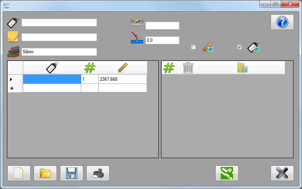
This will open the 1D nesting window. The part that was just created will be automatically added to the parts chart.
The project attribute fields will be at the top of the window. The left chart will be used for entering the individual part names, amounts needed, and length. To the right, a chart listing the number of full tubes needed, the amount of leftover tubing, and the number of parts that can be cut from the full tube will be generated.
Step 3
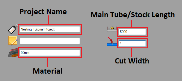
First, enter the project information. The fields at the top of the window will be used to supply this information. Enter "Nesting Tutorial Project" in the name field, 2500 in the main tube length field, and 6 in the cut width field. The material will automatically be filled in, so that field can be left alone.
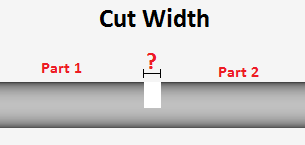
The main tube length (3500) is the total length of the piece of tube that will be used to create the parts. The cut width (6) is the amount of length that will be lost when creating a single cut.


