Difference between revisions of "Import Tutorial"
| (2 intermediate revisions by the same user not shown) | |||
| Line 32: | Line 32: | ||
==='''Note'''=== | ==='''Note'''=== | ||
| − | Before starting this tutorial, a part must be exported | + | Before starting this tutorial, a part must be completed then exported . This tutorial will be using the part file that was created in the '''[[Linear 2D Designer Tutorial]]''' and then exported in the '''[[Export Tutorial]]'''. |
| Line 230: | Line 230: | ||
| − | A menu will appear where a '''part designer can be chosen'''. Each designer will be represented by a button as shown in the image below. '''Click the XYZ button to bring the part into the XYZ part designer interface.''' (If XYZ isn't available, choose any of the other designer options.) | + | A menu will appear where a '''part designer can be chosen'''. Each designer will be represented by a button as shown in the image below. '''Click the XYZ button to bring the part into the XYZ part designer interface.''' ''(If XYZ isn't available, choose any of the other designer options.)'' The complete part design as well as the material and die will be transferred. |
'''''Note:''''' ''Depending on the version of software currently in use, fewer designer buttons may be included in this menu.'' | '''''Note:''''' ''Depending on the version of software currently in use, fewer designer buttons may be included in this menu.'' | ||
Latest revision as of 08:51, 28 August 2013
Contents
Introduction
This tutorial will step through the process of importing a basic part using the import plug-in.The import plug-in is used to bring .step/.stp, .iges/.igs, .brep part files into the software.
Tutorial
Note
Before starting this tutorial, a part must be completed then exported . This tutorial will be using the part file that was created in the Linear 2D Designer Tutorial and then exported in the Export Tutorial.
Step 1
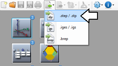
First, go up to the top of the window and click the import menu. Select the .step/.stp option from the list.
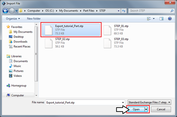
This will open the import file window where a file can be selected to import. Locate the Export_Tutorial_Part.stp file and click on it. Click the open button to move on to the next step.
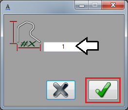
Next, another smaller window will appear. This is used to apply a scale to a part. This would only really be necessary if the part was created in measurement units different from the software. Make sure the number shown in the field is 1. Click the green check button.
Step 2
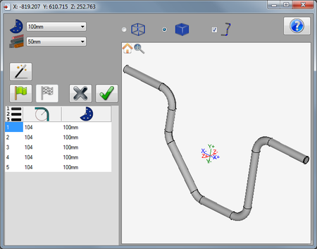
Now the import window will open. The die and material that the part was created with will be selected in the die and material menus. Since the part was able to be automatically defined when it was brought into the import interface, the complete part will be generated in the part display and bend chart will list each bend along with its CLR and die.
Even though the part is already defined, use the auto-define function to define the part again.
First, click the auto-define button. Now the part will be represented by just the circle, arc, and line features. Click on the first circle at the start of the part. The part will be defined completely and each bend will be generated in the bend chart again. See image below.
Note: At this point, the part could be brought into a part designer interface, but for the sake of the tutorial, the part will be re-defined again in the following steps.
Step 3
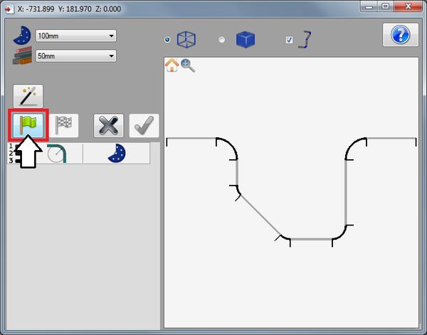
Now, the part will be re-defined by manually selecting features. First, click the start button (green flag).
Step 4
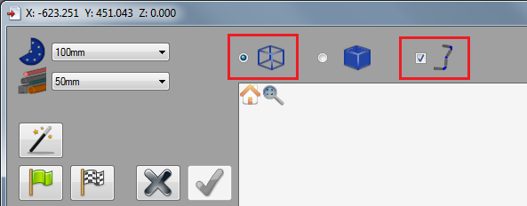
Now, at the top of the window, there are options that control how the part is displayed. Click the wire frame option and check the box next to the show part icon. The show part option will allow each part to be generated in the selected material as each section is defined.
Step 5
Next, the part will be defined using the circles and lines method.
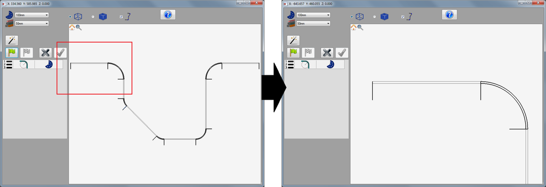
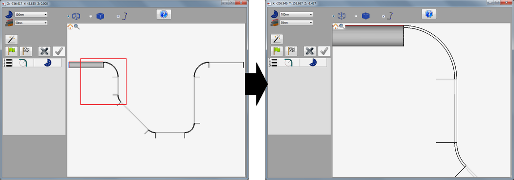
First, click the reset/home icon ![]() in the upper left corner of the display frame.
in the upper left corner of the display frame.
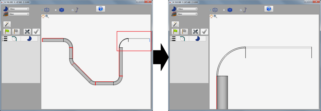
Now zoom in on the first length of the part on the left. To zoom in, first click within the part display frame then either use the mouse scroll wheel or press the plus [+] button on the keyboard. Adjust the view of the part so it looks somewhat like the image below on the right. Move/pan the part by holding both mouse buttons down and moving the cursor or by using the num pad keys (8 to move up, 2 to move down, 4 to move left, and 6 to move right).
Step 6
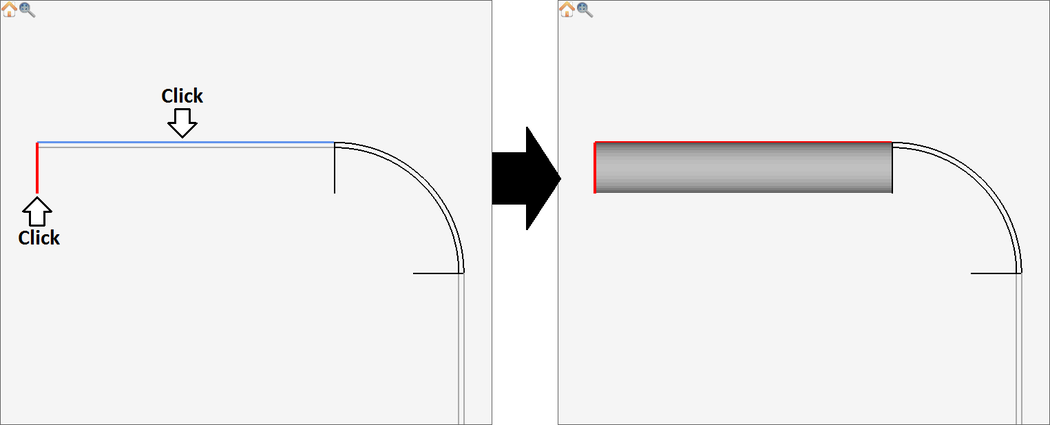
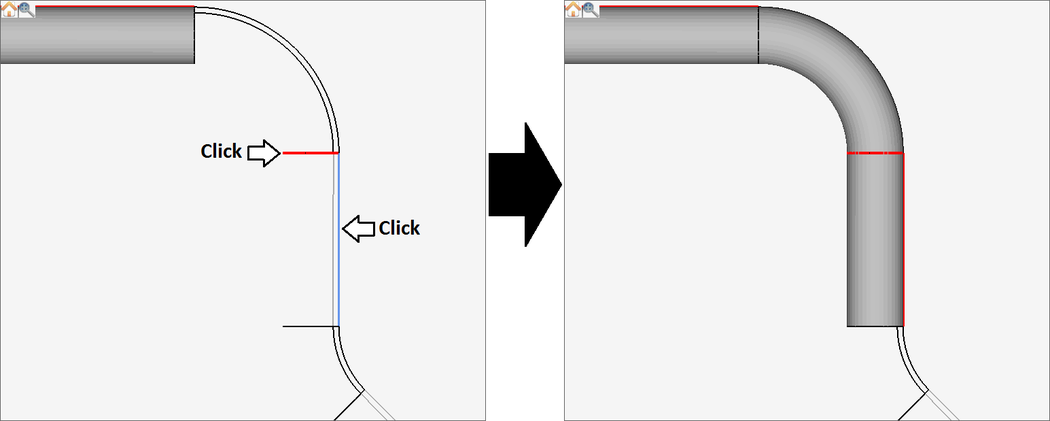
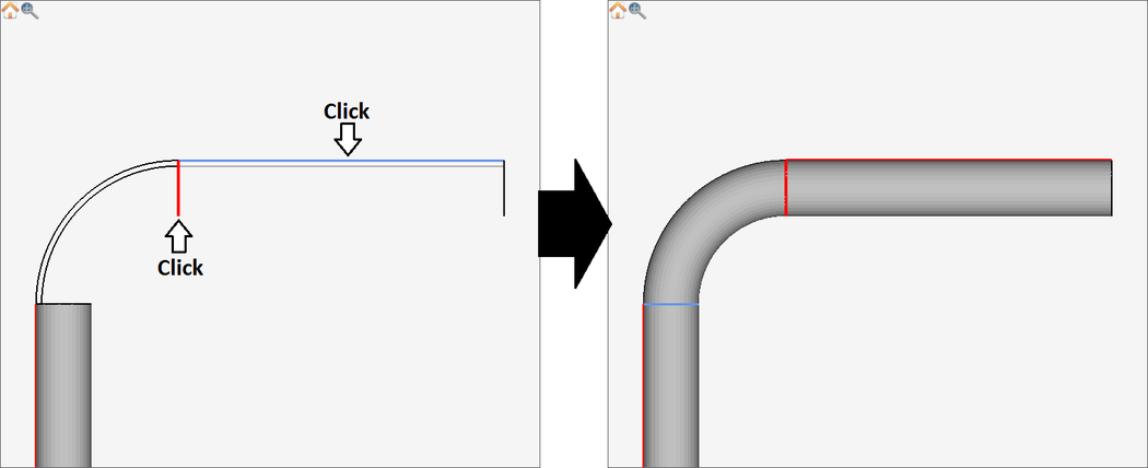
Now, the first length of the part will be defined. Click on the the outside circle feature at the starting end of the part to select it. Next, click the outside line that connects to the circle that was just selected. Once each feature is selected, the part length will be generated as shown below.
Step 7
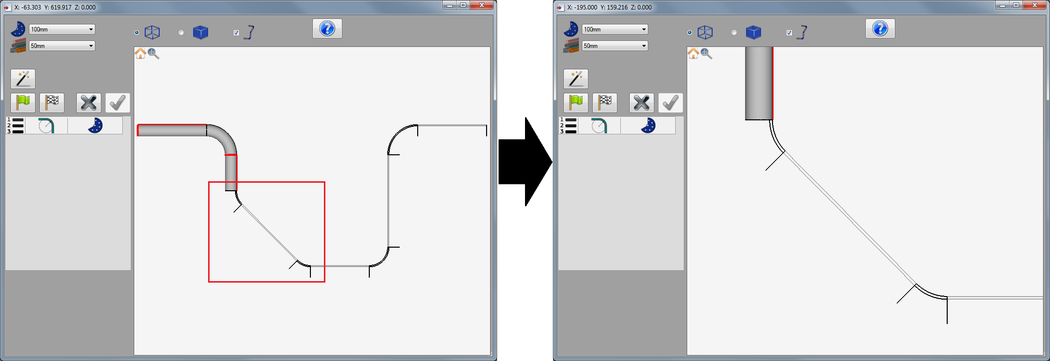
Now, click the home icon ![]() again. Then zoom in on the second straight length of the part, as shown below.
again. Then zoom in on the second straight length of the part, as shown below.
Step 8
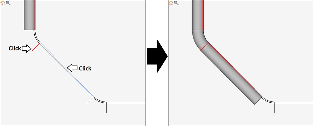
Now, the second length of the part will be defined. Click on the outside circle feature at the start of the length. Then, click on the outside line that connects to that circle. The next section of the part will be generated.
Step 9
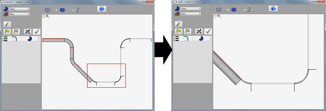
Now, click the home icon ![]() again. Then zoom in on the third straight length of the part, as shown below.
again. Then zoom in on the third straight length of the part, as shown below.
Step 10
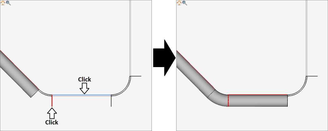
To define the third length of the part, click on the outside circle feature at the beginning of the length. Then, click on the line feature that connects to that circle.
Step 11
Now, click the home icon ![]() again. Then zoom in on the fourth straight length of the part, as shown below.
again. Then zoom in on the fourth straight length of the part, as shown below.
Step 12
To define the fourth length of the part, click on the outside circle feature at the beginning of the length. Then, click on the line feature that connects to that circle.
Step 13
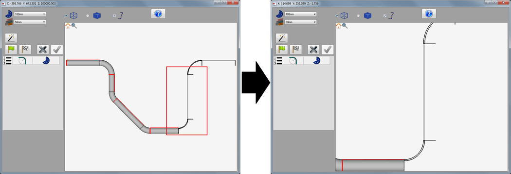
Now, click the home icon ![]() again. Then zoom in on the fifth straight length of the part, as shown below.
again. Then zoom in on the fifth straight length of the part, as shown below.
Step 14
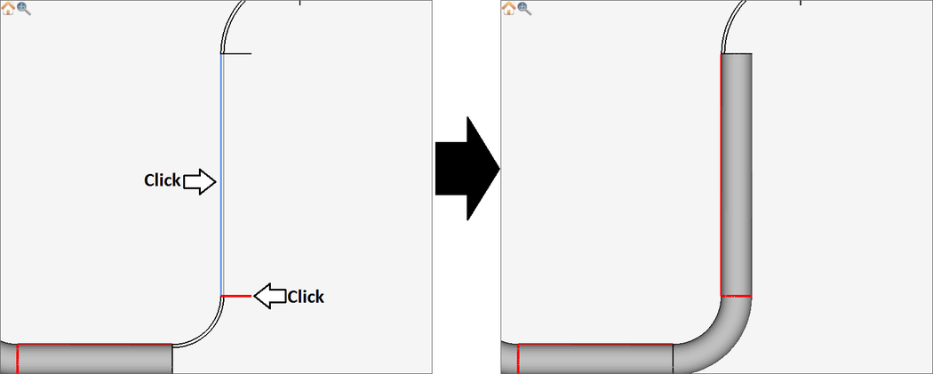
Define the fourth length of the part. Click on the outside circle feature at the beginning of the length. Then, click on the line feature that connects to that circle.
Step 15
Now, click the home icon ![]() again. Then zoom in on the very last straight length of the part, as shown below.
again. Then zoom in on the very last straight length of the part, as shown below.
Step 16
Now, finally, define the last length of the part. Click on the outside circle feature at the beginning of the part. Then, click on the line feature that connects to that circle.
Step 17
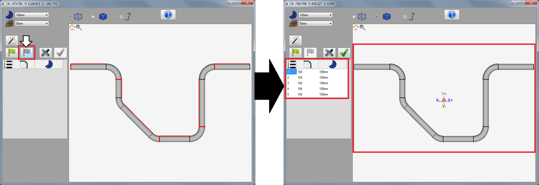
Now the part is fully defined. Click the home/reset icon ![]() . On the left side of the window, click the finish button (checkered flag). The bend information will be generated in the chart below. In this instance, the die that is selected in the die menu above is chosen for each bend.
. On the left side of the window, click the finish button (checkered flag). The bend information will be generated in the chart below. In this instance, the die that is selected in the die menu above is chosen for each bend.
Step 18
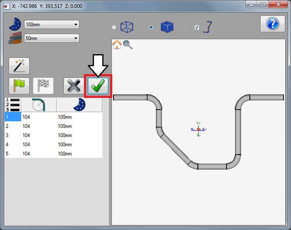
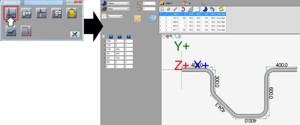
Next, the part can be brought into a part designer. Click the green check button.
A menu will appear where a part designer can be chosen. Each designer will be represented by a button as shown in the image below. Click the XYZ button to bring the part into the XYZ part designer interface. (If XYZ isn't available, choose any of the other designer options.) The complete part design as well as the material and die will be transferred.
Note: Depending on the version of software currently in use, fewer designer buttons may be included in this menu.
Step 19
The tutorial is complete!
For further information on the process of importing a part, see the Import page.
