Import
Contents
Description

Before a part can be fully imported, it must be defined in the import interface.
How To
To import a .step, .iges, or .brep part, follow these steps:
Start Up
1.) First, click the import menu on the main tool bar and select the file extension of the part that will be imported.

2.) Select a part in the Import File window and click the open button.

Scale
3.)
For example, this can be used to convert parts that were created in inches to millimeters by using a scale value of ".03937". A scale of "1" will mean the part size will remain the same. Increasing or decreasing this scale value will change the size of the entire part. The die and material will also be adjusted accordingly. If the dies and materials available don't match up exactly with the scale provided, the die and material with the closest appropriate sizes will be chosen automatically in the import window.
To adjust the scale, enter a value into the scale field and click the green check to continue.
Import Controls and Options
4.)
In some cases, the part may be automatically defined at this point. To tell if a part has been automatically defined, look at the part in the part display and the bend chart. If the part is shown in the selected material and it's not just the skeleton of the part, and the bend chart has been generated, it has been already defined. See image to the right to see what this would look like. If no adjustments are necessary and the part has been auto defined, the green check button can be clicked at the part will be imported.
If the part is not automatically defined, it will need to be manually defined.
Die/Material Menus and Part Options
In the upper left corner, there are two menus that represent the material and die of the part. To the right of these menus, there will be three part options shown above the part display.

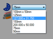
- Die menu:The die chosen here will be the default die that is set in the die library. If a part is defined without selecting arcs, the die selected here will be chosen for each bend once the part is defined. To select a die, click the drop down menu and select a die from the list, as shown to the right. All the dies in the die library will be included in the list.

Note: After a part has been completely defined, changing dies here will not affect the part. See the Bend Chart section for information on changing each bend's die after defining a part.
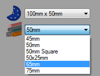
- Material menu:The material of the part can be chosen using the material menu. The part model in the import window will be shown in this material and the part will be imported in this material. To choose a new material, click the drop down menu and select a material from the list, as seen to the right. Every material in the material library will be included in this list.

- Wire frame/shaded model: Once the part is fully defined, the part model can be viewed in wire frame or as a shaded model. To switch between these two viewing options, use the wire frame and shaded options shown above the part display.

- Show part: While the box next to the show part icon is checked, each section of the part will be generated as the part is being defined. In the image below, the first section of the part has been defined, and since show part is on, the section is shown in the selected material.

Manual Definition
The process of manually defining parts consists of clicking on the part's features to select them. As features are selected, they will be highlighted in red. These highlighted features will be the features that will be included in the final imported part. During the import process, each part feature will be represented by lines, shapes, and circles.
There are a number of ways to define a part manually. Depending on what kind of features the part has, certain methods may be more appropriate. See the Import - Manual Definition page for an explanation on how each method works.
Auto Definition
In some situations, the part may be automatically defined. This will work well with very basic parts similar to the part in the example image.
To auto define a part, first click the auto define button. ![]() After clicking this button, click on any of the feature lines on the part in the part display to the right. If successfully defined, the part will be generated in the chosen material and the bend information will be listed in the bend chart on the left of the window. See image below.
After clicking this button, click on any of the feature lines on the part in the part display to the right. If successfully defined, the part will be generated in the chosen material and the bend information will be listed in the bend chart on the left of the window. See image below.
Note: If auto define doesn't work the first time, it may be helpful to try again and click on a different part feature.

Bend Chart

The ability to choose a die for each individual bend will be available here. To change an individual bend's die, click on the die name in the bend's row and click the drop down menu. Select a die from this list.

Part Display Controls
The view of the part in the part display can be adjusted using mouse controls and the icons in the upper left corner.
To zoom in and out, use the mouse scroll wheel. Scroll down to zoom in and scroll up to zoom out.
To pan/move the part around, click and hold both mouse buttons and move the cursor around the frame. The part will follow the cursor.
To rotate the part, click and hold down the right mouse button and move the cursor around.
To reset the part to the default view, click the house icon ![]() in the top left corner.
in the top left corner.
To zoom all the way in on the current part orientation, click the magnifying glass icon ![]() in the top left corner. See image below.
in the top left corner. See image below.

Finalize Import

To import the part, click the green check button. ![]() (If the part isn't fully defined, the green check button will not be available.) A message box will appear where the a designer can be chosen - shown to the right. (Note: The designers shown here will depend on which version of the software is currently in use.)
(If the part isn't fully defined, the green check button will not be available.) A message box will appear where the a designer can be chosen - shown to the right. (Note: The designers shown here will depend on which version of the software is currently in use.)
Choose a designer by clicking on one of the provided icons. Once a designer is chosen the part will be fully imported and further edits can be done within the designer interface. The chosen dies and the material will be brought into the designer interface with the part.
