Graphical Display
Description
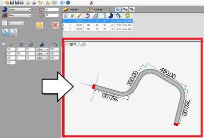
In each designer, a model of the part will be generated in the graphical/part display to the right of the design panel.
The view of the part model can be controlled by moving, rotating, zooming, and/or using the display icons.
How To
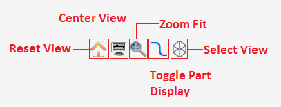
Display Control Icons
- Reset View: Click the reset view/house icon to set the part orientation back to the default view. This will bring the part model back to how it was displayed before any view adjustments were made.
- Center View: Click the center view icon to set the part to the center of the screen at its current rotated view. This will zoom in on the part and bring it to the very center of the graphical display.
- Zoom Fit: Click the zoom fit icon to zoom all the way in on the part model and fit it to the graphical display.
- Toggle Part Display: Click the toggle part display icon to turn on or off the part dimension markers and values, apex guides, and directional axis in the bottom left corner. See image below.
- Note: If the display dimensions option is deactivated in the global settings or if a machine is in use and the machine has the display dimensions option deactivated, the toggle part display icon will toggle the directional axis.
- Select View: The select view icon allows the part to be viewed from a specific direction. To choose a new viewing direction, click the select view icon. Once clicked, a set of icons will appear next to the select view icon. Each represents a different direction.


