Machine Library
Contents
Description

The machines defined in the machine library can be chosen during the part design process and these machine settings will be applied to the part.
The machine library window is divided into three sections. The left side of the window holds the machine list with the add and remove buttons. The machine name and default check box are at the very top of the window. The settings tabs are located to the right of the machine list. When a machine is selected in the machine list, its name and settings will be shown.
How To
Start Up
To access the machine library, click the settings menu on the main tool bar. Click the machine library option in the drop down menu.

Add Machine

Edit Machine
To edit a machine, first click on the machine in the machine list to select it. Once the machine is selected, change any of the attributes and machine settings. Be sure to click the save button ![]() to apply any of the changes made to the machine.
to apply any of the changes made to the machine.
Name and Default

- Machine Name: The name of machine. The name given here will be what this machine is called throughout the software.
- Default Check Box: While the default box is checked, the current machine will be set as the default machine. The default machine will be automatically chosen in the machine menu whenever a new part design is opened.
Defaults Tab
In the Defaults tab, the default notes, default cut-offs, and dimension display can be set.

- Notes: The default notes given here will be added to the part design's notes section when the machine is selected. But, if the part design's notes were edited prior to adding the machine, these notes will not be applied to the part.
- Cut-off Start/End: These cut-off values are the amount of extra material needed on either end of the part when bending tubes with this machine. The cut-off values supplied here will be the cut-off values applied to the part when the machine is selected. To add cut-off values, enter values into either of these fields.
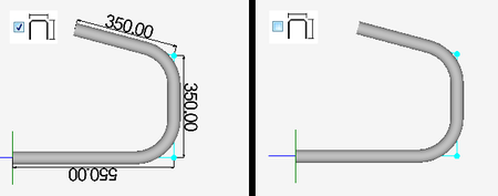
- Display Dimensions:While the display dimensions box is checked, the part model will be shown with the dimension markers and the length measurement values in the part display. While this box is not checked, just the part model and the apex lines/points will be displayed. See image to the right.

Results/Output Format

Notice how when a format is selected, an example of how the dimensions will be measured is shown to the right. The example part is a flat layout of a simple part that is 100 units long. The bends are sectioned off with grey lines.
The settings are shown to the right of the format options. Whenever a predefined option is selected They will be greyed out/unavailable, but they can still be seen. See image to the right.

- Rotary Draw: This format is for standard rotary draw benders. These kind of benders have a die that spins and pulls the material around it. The dimension location is at the start of the bend and there is no fixed offset.
- Center Compression: This format is for center compression benders. The die can move, but doesn't rotate/spin and the material is pushed around it. The dimension location is at the center of the bend and there is no fixed offset.
- Rotary Compression: This format is for rotary compression benders. The die is stationary (No moving or spinning) and the material is pushed around the side of the die. The dimension location is at the end of the bend and there is no fixed offset.
- Length of Straight: This format will only include the straight lengths of tube. To get just straight lengths of tube when designing, this option must be chosen.
- Custom: The dimension location, fixed offset and can be chosen individually using the custom format.
- Dimension Location: This will determine where the end of the dimension will be placed. The start of bend, center of bend, or end of the bend can be selected. Click on a dimension location option to select it.

- Utilize Part Length: When the utilize part length check box is checked, the location values will be based off of the total length of the part. Each location values will be calculated by either adding or subtracting the original bend location value from the part length measurement. Click on the green plus to add the location to the part length or click the red minus option to have the locations subtracted from the part length. When the red minus option is selected, the location is essentially being measured from the opposite end.

- Fixed Offset: The fixed offset setting will allow a value to be added or subtracted from the location value. This will be necessary to apply when an indexing table is used with the machine. To add a fixed offset value, enter the offset value into the provided field. Click the green plus option for the offset value to be added to each location or click the red minus option for the offset to be subtracted from each location.

Results/Output Settings
The decimal tolerances, rotation settings, and bender type for the machine can be chosen within the Results/Output tab.

- Decimal Tolerances: The decimal tolerance for the lengths, angles, and rotations can be adjusted here. This will affect the dimensions that are displayed on the 3D part model and the values in the results table. The decimal tolerance controls how many digits will be allowed after decimals points for length, angle, and rotation values. In the tolerance options, each digit place is represented by an n.
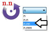

- For example, if the angle tolerance is set to n.nn and the actual angle is 90.539°, the angle will be rounded to 90.54°. If the angle tolerance is set to just n, then the angle would be rounded to 90°.
- To change the decimal tolerance for the length, angle or rotation, click the drop down menu next to the appropriate option and select an option from the list. See image to the right.
- Rotation Settings: The rotation settings control how rotation values are displayed in the results table. Rotation can be measured in incremental or absolute terms. Each rotation angle range can also be chosen.
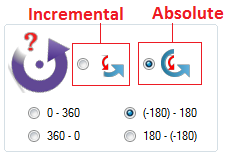

- Incremental: Rotation angles will start from the end of the previous bend's rotation. Click the incremental rotation option to select it.

- Absolute: Rotation angles will always start from the very beginning of the angle scale. Click the absolute rotation option to select it.

- Rotation Angle Scale: The rotation scale will determine what the rotation angles will range between. The rotation scale will show where the angle measurements begin and where they end. Choose a rotation scale by clicking on one of the scale options. The rotation scales available are 0 - 360, 360 - 0, (-180) - 180, and 180 - (-180).
- Bender Type: The type of the current bending machine can be chosen by clicking the bender type button.
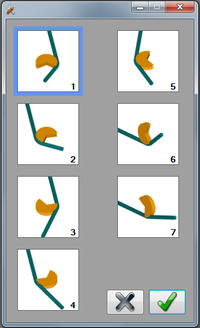
 This will open the bender type menu (Shown to the right). Seven bender types are available. Each type is represented by a tile that displays a short animation of what a bender of that type will look like while bending a part. To select the bend type for the machine, click on a tile. The selected bend type will be outlined in blue. Click the green check button to confirm.

- Note: If the simulation plug-in is installed, the bender type chosen here will be automatically selected in simulation when the machine is chosen for the current part.
Delete Machine
To delete a machine from the library, first select the machine from the list by clicking on it. Once the machine is selected, click the delete button ![]() to remove it.
to remove it.

Help Videos

Click on any of these help icons to watch help videos that will visually explain certain attribute or how to use a certain button or function. See image below. Use the play, pause and stop buttons in the bottom left corner of the window to control the video. Click the grey X button ![]() to close the video.
to close the video.

Machine Menu
Once any machines are added to the machine library, they can be selected in any of the part designers using the machine menu. When a machine is selected, all of the settings chosen for the machine in the machine library will be applied to the part and will override the program settings. If a machine is set as the default, that machine will automatically be chosen in this menu when a new part design is opened.

When a machine is selected, it will have a check mark next to the machine name in the machine menu, as shown below.
