Machine Library Tutorial
Contents
Introduction
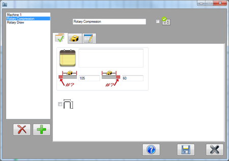
This tutorial will step through the process of adding two different machines (Rotary draw and rotary compression) to the machine library using the machine library plug-in.
The machine library plug-in is used to create different machines by assigning specific settings to them. These settings include the way rotations and lengths/locations are measured, the decimal tolerances for lengths, angles, and rotations, and default cut offs. Machines are selected during the part design process and all the machine's settings will be applied to the part.
Tutorial: Rotary Draw Machine
Step 1
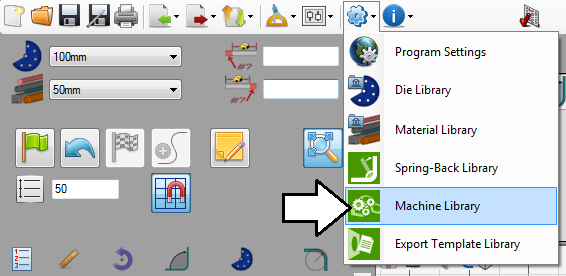
First, open the machine library. Go up to the main menu bar and click on the settings menu. Select the machine library option from the drop down menu.
Step 2
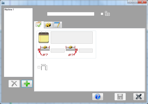
This will open the machine library. A list of the machines will be shown to the right. To the left, there will be a tabbed section where the machine settings will be chosen.
Step 3
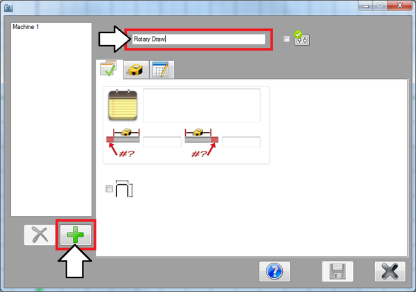
Now the first machine will be created. Click the add button. Enter the machine's name, "Rotary Draw", in the field above the tabs near the top of the window.
Step 4
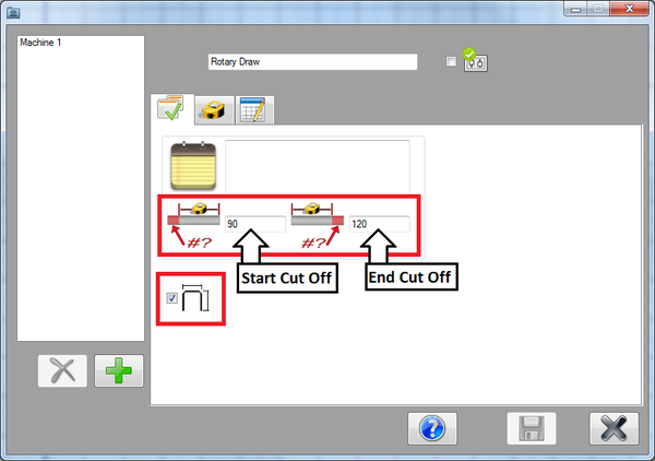
In the first tab, the default settings can be chosen.
In the start cut off field, enter 90. In the end cut off field, enter 120.
Check the box next to the dimension display icon. When checked, the part model in the part designer will include the dimension markers and values.
Step 5
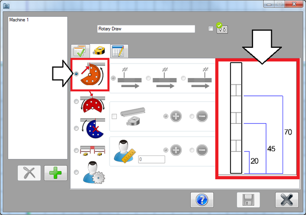
Next, click on the second tab. In this tab, the format of the results table can be chosen.
Since this machine is going to be a rotary draw machine, select the pre-defined rotary draw option.
Dimensions will start at the beginning of the part and end at the start of each bend. An example of how the dimensions will be placed are shown to the left of the format selection area.
Step 6
Now click on the third tab. This is where the decimal tolerances, rotation settings, and bender type can be set.
The decimal tolerances control how many digits are allowed after decimal points for length, angle, and rotation values.
Select the 'n.nn' option for both length and angle. For rotation, select 'n'.
