Simulation
Contents
Description
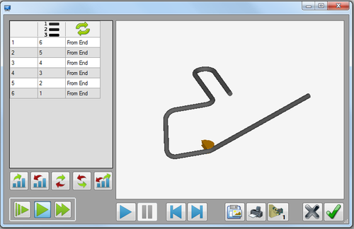
The simulation plug-in shows a basic animation of the part moving through the die. The bend order, the speed of the simulation, and the bending type can be adjusted. There is also the option to save or print the current view of the part in the bending process.
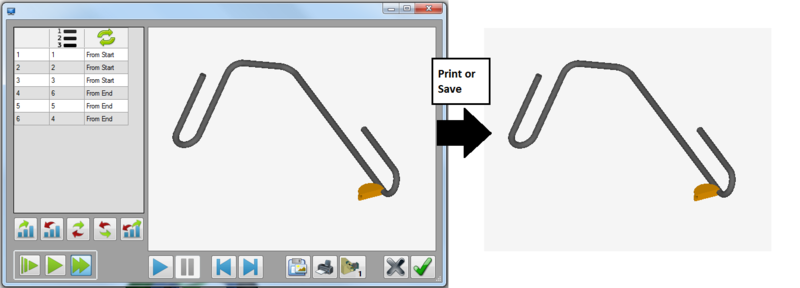
The left panel shows a list of the bend numbers, current bend order, and orientation of each bend. Below the bend list, there are buttons that can be used to control the order and orientation of the bends. The speed control buttons are located at the bottom of the left panel. The part simulation frame is located to the right of the window. The simulation controls as well was the bend style, save, and print buttons are located below the simulation frame.
How To
Start Up
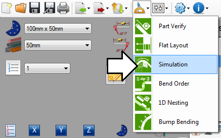
To access simulation, click on the tools menu on the main tool bar. Click the simulation option in the drop down menu, as shown below.
Controls and Options
Bend Order
The order and orientation of the bends can be adjusted. Any changes made to the bending order in the simulation window will affect the actual bend order settings, the results table bend order, and the bending order on the setup sheet. When the bending order is changed, the simulation will bend the part according to the current order of bends.
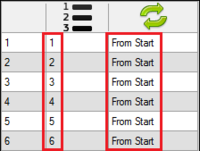
To set the bends to the normal bend order, click the normal bend order button. ![]() The bending process will start at the first bend and end at the last bend. Each bend will be bent starting at the beginning/start of the bend.
The bending process will start at the first bend and end at the last bend. Each bend will be bent starting at the beginning/start of the bend.
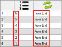
To completely reverse the bend order and orientation, click the reverse bend order button. ![]() The bending process will start with the last bend and end with the first. Each bend will be bent starting from the end of the bend.
The bending process will start with the last bend and end with the first. Each bend will be bent starting from the end of the bend.
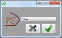
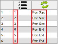
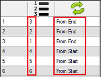
To flip the bending order and orientation between two bends, click the normal flip button. ![]() Once that's clicked, a message box will appear. Click the drop down menu and choose which bends the flip will occur between. Click the green check button to confirm. This will cause the bend order to completely flip between the specified bends. For example, if '3&4' is chosen, the bend order will go in order and bend from the start of the bend up to bend three. After bend three, the order goes in reverse order and the bend's are bent from the end of the bend.
Once that's clicked, a message box will appear. Click the drop down menu and choose which bends the flip will occur between. Click the green check button to confirm. This will cause the bend order to completely flip between the specified bends. For example, if '3&4' is chosen, the bend order will go in order and bend from the start of the bend up to bend three. After bend three, the order goes in reverse order and the bend's are bent from the end of the bend.
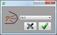
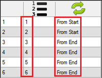
To flip the bend orientation between two bends, click the opposite flip button. ![]() Once that's clicked, a message box will appear. Click the drop down menu and choose which bends the flip will occur between. Click the green check button to confirm. This will cause the bend orientation to completely flip between the chosen bends. The bend order will remain normal, but the orientation will switch from 'From Start' to 'From End' between the bends.
Once that's clicked, a message box will appear. Click the drop down menu and choose which bends the flip will occur between. Click the green check button to confirm. This will cause the bend orientation to completely flip between the chosen bends. The bend order will remain normal, but the orientation will switch from 'From Start' to 'From End' between the bends.
To start the bend order at the center and work towards start/end, click the center out button. ![]() Once the button is clicked, a message box will appear. Click the drop down menu and choose which bends bend order will be split between. The bend order will go in reverse order starting between the two chosen bends working to the start of the part bending each bend from the end of the bend. After the first bend on the part is complete, the bend order will return to normal and work towards the end of the part bending each bend from the start of the bend.
Once the button is clicked, a message box will appear. Click the drop down menu and choose which bends bend order will be split between. The bend order will go in reverse order starting between the two chosen bends working to the start of the part bending each bend from the end of the bend. After the first bend on the part is complete, the bend order will return to normal and work towards the end of the part bending each bend from the start of the bend.
Speed Controls
The speed of the simulation can be adjusted using the speed controls. The first button will set the animation to the slowest setting, the middle button will set the animation to the normal speed, and the last button will set the animation to the fastest speed. The speed can either be adjusted before the animation plays or while the animation is playing.
Video Controls
The buttons below the simulation frame are used to control the animation of the bending part. The simulation will reflect the bend order that is displayed on the left panel.
The first button on the left is the play button. Clicking this button will start the animation from the current position.
The second button in is the pause button. Clicking this button will stop and hold the animation at the current position of the bending process.
The third button in is the restart button. Clicking this button will set the animation back to the beginning of the bending process.
The last button is the finish button. Clicking this button will set the animation to the end of the bending process and show the completed part.
Adjust View
The view of the part animation can be adjusted using mouse controls.
To zoom in or out, use the mouse scroll wheel. Scroll up to zoom out and scroll down to zoom in.
To pan/move the part around the frame, click and hold both mouse buttons. Move the cursor around the frame and the part will follow.
To rotate the part, click and hold the right mouse button. Move the cursor around the rotate the part.
Save and Print
An image of the current state of the simulation can be saved or printed out. When saving or printing the simulation, whatever is currently shown in just the simulation part display frame will be saved or printed. See image below.
To save an image, click the save button. ![]()
To print an image, click the print button. ![]()
Bend Type
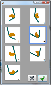
The bending type used during the simulation can be changed. Any of the following can be chosen: clockwise, counter clockwise, rotary draw, rotary compression or center compression.To change the bending type, click the bend type button. ![]() (Note: The button will display the number that corresponds to the current bend type in use.) After the button is clicked, the bend type menu will open. Each bending type will be represented by a short animation of what the bend type looks like while bending, as seen to the right. Select a bend type by clicking on a bend type tile and then click the green check button.
(Note: The button will display the number that corresponds to the current bend type in use.) After the button is clicked, the bend type menu will open. Each bending type will be represented by a short animation of what the bend type looks like while bending, as seen to the right. Select a bend type by clicking on a bend type tile and then click the green check button.
OK/Cancel
To save and exit the simulation, click the green check button. ![]() This will save all bend order adjustments and the bend type. The bend order will be included on the part setup sheet.
This will save all bend order adjustments and the bend type. The bend order will be included on the part setup sheet.
To exit the simulation without saving any of the bending order or bend type settings, click the cancel button. ![]()
