Die Library
Contents
Description

Each die can be calibrated using the calibration function and there is a list of predefined dies from a number of different bender models.
In the die library window, there is a list of all dies in the library on the left. The add and delete buttons are located below this list. To the right, the attributes of the currently selected die are shown. The calibration, die list, and save buttons are situated below the attribute fields.
How To
Start Up
To access the die library, click on the settings menu on the main tool bar. Click the die library option in the drop down menu.

Attributes
Each die is defined by a set of attributes. See image below.
Note: In any of the attribute fields, only supply numerical values. Do not supply units in these fields.

- Die Name: The name given to the die. This will be the what the die is called throughout the software.
- Achieved CLR: The CLR that the die will actually produce when bending. This value compensates for spring-back and other factors that contribute to inaccuracies in the CLR of a bend.
- Calibrated CLR: This is a value that is generated and used by the software to ensure accuracy. In general, this value should be 5 to 20% larger than the achieved CLR (the actual CLR that the die will produce). To get this value, the calibration wizard or the OEM die list must be used.
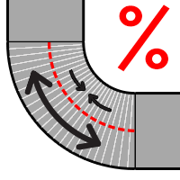
- K Factor:K Factor is defined as the percentage through the inside radius to the neutral bending axis (See image to the right). Basically, this is the location of the line that runs through the bend where there is no stretching or compression, AKA the neutral bending axis. K factor is measured from the inside edge/radius of the bend to the neutral bending axis on a scale of 0 - 100 or 0 - 1 where 0 is the inside edge/radius of the bend and 100 or 1 is the outside edge/radius of the bend. Everything on the inside of the K factor is compressing and everything on the outside is stretching.

- Note: Each die can use either calibrated CLR or K factor, but not both. If both are entered, the software will default to the K factor. So, to use the Calibrated CLR, the K factor field must be left blank.
- Bend Location Offset: The offset distance between the mark on the tube and the actual starting point of the bend. For example, if the bend offset is 0, the bend starts exactly where the mark is placed.
- Default: When the default check box is checked, the currently selected die will be the default die. The default die will be automatically selected in the die selection menu when a new part design is opened.
- Minimum Start Length: This is the shortest amount of tube length allowed at the very beginning of the tube before the first bend. This measurement will start at the starting end of the tube and end at the start of the first bend when the bend is as close to the starting edge as possible.
- Minimum End Length: This is the shortest amount of tube length allowed at the end of the tube after the last bend. The measurement will begin at the ending edge of the last bend and end at the end of the tube when the bend is as close to the end of the tube as possible.
- Minimum Distance Between Bends without Rotation: This is the shortest amount of tube length allowed between bends that have no rotation.
- Minimum Distance Between Bends with Rotation: This is the shortest amount of tube length allowed between bends that have rotation. For example, the distance allowed between two bends with a 180° between them.
- Note: The minimum start length, minimum end length, minimum distance between bends without rotation, and minimum distance between bends with rotation will be used to check for manufacturing errors if the manufacture checking plug-in is included with the current version of software.
Add Die
Manual Entry
To manually add a die to the die library, click the add button ![]() below the die list. After add is clicked all the attribute fields to the left will be cleared out. Enter the information into these fields and click the save button
below the die list. After add is clicked all the attribute fields to the left will be cleared out. Enter the information into these fields and click the save button ![]() to add the die to the library.
to add the die to the library.

OEM Die List

A list of all the dies currently in the library will be shown on the left side of the window. In the middle there will be a machine/bend drop down menu and a selection menu where the material shape and measurement can be chosen. Below the menus, the die information will be shown once a die is selected from the right die list. To the far right, a list of available dies for the machine and material will be shown once a machine is selected.
To add a die from the OEM die list, first a machine must be selected. Click on the drop down menu and choose a machine from the list.


When a die is selected, it's attributes will be generated. The stamped CLR, achieved CLR, calibrated CLR, minimum distance before bend, and serial number will be displayed.

- Stamped CLR: The CLR value that the die was given. Typically this is stamped directly onto the die.
- Achieved CLR: The CLR that the die will actually produce when bending. See the achieved CLR definition in the Attributes section.
- Calibrated CLR: The calibrated CLR of the die. See the calibrated CLR definition in the Attributes section.
- Bend Location Offset: The die's bend location offset. See the bend location offset definition in the Attributes section.
- Serial Number: The die's serial number.
Once the proper die has been found and selected, click the add button ![]() to add it to the die library. A message box will appear where a new name can be applied to the die. Give the die a new name or keep the default name then click the green check button to add it to the library. Once added, it will also appear in the die library list on the left of the window.
to add it to the die library. A message box will appear where a new name can be applied to the die. Give the die a new name or keep the default name then click the green check button to add it to the library. Once added, it will also appear in the die library list on the left of the window.


Dies can also be deleted from the die library within the OEM Die List window. To delete a die, select the die in the die library list by clicking on it. Click the delete button ![]() to remove it.
to remove it.
Edit Die
To edit a die's attributes, first select the die by clicking on it in the die list. Change the values as necessary and click the save button ![]() to confirm the changes made.
to confirm the changes made.

Remove Die
To remove a die from the die library, first select the die by clicking on it, then click the delete button. ![]()

Die Calibration Wizard

To access the die calibration wizard and calculate the calibrated CLR for a specific die, select a die in the die list and click the calibration wizard button. ![]() Another window will open that will step through the process of finding the calibrated CLR. Use the blue arrow buttons at the bottom of the window to navigate.
Another window will open that will step through the process of finding the calibrated CLR. Use the blue arrow buttons at the bottom of the window to navigate.
At the end, the achieved CLR, calibrated CLR, and the bend location offset will be displayed, seen in the image to the right. Click the green check button to confirm and generate these values in the appropriate fields of the current die. In the die library window, click the save button to save the new values.
Warning: Calibrated CLR should be 5 to 20% larger than the achieved CLR. If the calibrated CLR result does not reflect this, please go back through the calibration wizard and double check the values.
Help Videos

Click on any of these help icons to watch help videos that will visually explain certain attribute or how to use a certain button or function. See image below. Use the play, pause and stop buttons in the bottom left corner of the window to control the video. Click the grey X button ![]() to close the video.
to close the video.
