Die Library
Contents
Description
The die library stores all the dies available to bend parts. Each die is assigned a set of attributes such as name, stamped CLR, calibrated CLR, minimum distance before a bend, minimum start length, minimum end length, and minimum distance between bends with and without rotation.
Each die can be calibrated using the calibration function and there is a list of predefined dies from a number of different bender models.
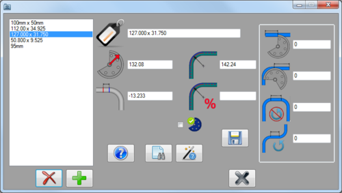
In the die library window, there is a list of all dies in the library on the left. The add and delete buttons are located below this list. To the right, the attributes of the currently selected die are shown. The calibration, die list, and save buttons are situated below the attribute fields.
How To
Start Up
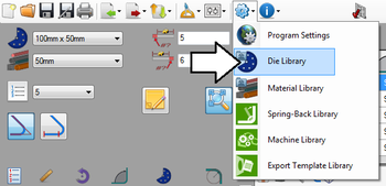
To access the die library, click on the settings menu on the main tool bar. Click the die library option in the drop down menu.
Attributes
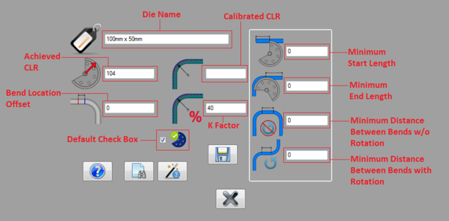
Each die is defined by a set of attributes. See image below.
- Die Name: The name given to the die will be the what the die is called throughout the software.
- Stamped CLR: This CLR is what the die was sold as. Typically, this is stamped directly onto the die itself.
- Calibrated CLR: This CLR is the CLR measurement that the die actually bends to.
- Minimum Distance Before Bend: This is the shortest amount of length that is allowed before a bend begins.
- Minimum Start Length: This is the shortest amount of length allowed at the very beginning of the tube before the first bend.
- Minimum End Length: This is the shortest amount of length allowed at the end of the tube after the last bend.
- Minimum Distance Between Bends without Rotation: This is the shortest amount of tube length allowed between bends that have no rotation.
- Minimum Distance Between Bends with Rotation: This is the shortest amount of tube length allowed between bends that have rotation.
Add
Dies can be added using two different methods.
1.) By manually entering the die information. First, click the add button ![]() below the die list. After add is clicked all the attribute fields to the left will be cleared out. Enter the information into these fields and click save to add the die to the library.
below the die list. After add is clicked all the attribute fields to the left will be cleared out. Enter the information into these fields and click save to add the die to the library.
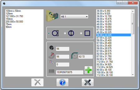
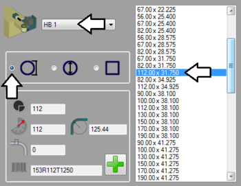
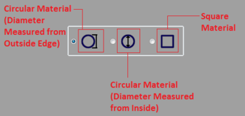
A list of all the dies currently in the library will be shown on the left side of the window. In the middle there will be a machine/bend drop down menu and a selection menu where the material shape and measurement can be chosen. Below the menus, the die information will be shown once a die is selected from the right die list. To the far right, a list of available dies for the machine and material will be shown once a machine is selected.
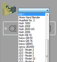
To add a die from the OEM die list, first a machine must be selected. Click on the drop down menu and choose a machine from the list.
