Difference between revisions of "Linear Advanced Designer"
(→Controls and Options) |
|||
| (12 intermediate revisions by the same user not shown) | |||
| Line 1: | Line 1: | ||
==Description== | ==Description== | ||
| − | [[File:linadv.png|right| | + | [[File:linadv.png|right|500px]] The Linear Advanced Designer allows parts to be created in full 3D. Parts are designed by choosing the number of bends and supplying length, rotation, and angle values. The way the dimensions are placed on either side of each bend can be customized as well. |
| + | |||
| + | |||
| + | |||
| + | |||
| + | |||
| + | |||
| + | |||
| + | A tutorial on how to create a part using this designer is available here: '''[[Linear Advanced Designer Tutorial]]''' | ||
| + | |||
| + | |||
| + | |||
| + | |||
| − | |||
| − | |||
| − | |||
| Line 18: | Line 27: | ||
| + | ==How To== | ||
| + | |||
| + | |||
| + | ===Start Up=== | ||
| + | To access this designer, click the linear advanced button [[File:linadvicon.png]]. This will open a new, blank part design. | ||
| Line 23: | Line 37: | ||
Once a new linear advanced part design window has been opened, a new part can be created. | Once a new linear advanced part design window has been opened, a new part can be created. | ||
| − | [[File:matdiecut.png|right]]First, a '''die and material''' should be chosen. This can be done by clicking on the drop down menus next to the die and material icons in the top left corner of the screen. | + | [[File:matdiecut.png|right]]First, a '''[[Die Library|die]] and [[Material Library|material]]''' should be chosen. This can be done by clicking on the drop down menus next to the die and material icons in the top left corner of the screen. |
If any '''cut-off''' is necessary, enter the amount needed into the start and end cut-off fields. The first/top field represents the cut-off at the start of the part and the second/bottom field represents the cut-off at the end of the part. | If any '''cut-off''' is necessary, enter the amount needed into the start and end cut-off fields. The first/top field represents the cut-off at the start of the part and the second/bottom field represents the cut-off at the end of the part. | ||
| Line 40: | Line 54: | ||
| − | '''To start designing the part''', enter values into the designer entry fields on the left panel. Each bend and the last straight length will have its own row. The '''first column''' represents the dimension type for the | + | '''To start designing the part''', enter values into the designer entry fields on the left panel. Each bend and the last straight length will have its own row. The '''first column''' represents the dimension type for the start of the dimension. The '''second column''' below the ruler icon represents the straight lengths of tube. The '''third column''' below the arrow icon represents the rotations for each bend. The '''fourth column''' below the angle icon represents the angle of each bend. The '''fifth column''' represents the dimension type for the end of the dimension. See image below. |
[[File:lapart01.png|400px]] | [[File:lapart01.png|400px]] | ||
| Line 46: | Line 60: | ||
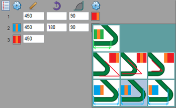
| − | [[File:lapart03.png|right|350px]]'''Changing the dimension type''' will affect the way the | + | [[File:lapart03.png|right|350px]]'''Changing the dimension type''' will affect the way the dimensions are placed on either side of each bend. This is done by clicking the colored icons on either end of the bend rows. Once clicked a menu of all dimension types available will be shown. Click on one to select it, as shown to the right. |
| + | |||
| + | |||
| + | |||
| + | |||
| + | |||
| + | |||
| + | |||
| + | |||
| + | |||
| + | |||
| − | |||
| − | |||
| − | |||
| + | |||
| + | '''For example''', on the second bend, the first column of dimension types will affect the dimension on the far end of the bend and the second dimension column will affect the end closest to the bend. See image below. | ||
| + | [[File:lapart02.png|700px]] | ||
| − | |||
| − | |||
| − | + | ====Dimension Types==== | |
| − | *[[File: | + | *[[File:dimtype01.png]] '''Tangent:''' The dimension will go to the tangent of the bend. |
| − | *[[File: | + | *[[File:dimtype02.png]] '''Outside Apex:''' The dimension goes along the outside of the tube to the apex of the bend. |
| − | *[[File: | + | *[[File:dimtype03.png]] '''Center-line Apex:''' The dimension goes along the center-line of the tube to the apex of the bend. |
| − | *[[File: | + | *[[File:dimtype04.png]] '''Inside Apex:''' The dimension goes along the inside of the tube to the apex of the bend. |
| − | *[[File: | + | *[[File:dimtype05.png]] '''Outside Perpendicular:''' The dimension goes along the tube to the perpendicular point on the outside of the bend. (''Note: Should be used on bends of 90° or greater for it to have an effect.'') |
| + | *[[File:dimtype06.png]] '''Center-line Perpendicular:''' The dimension goes along the tube to the perpendicular point in the center of the bend. (''Note: Should be used on bends of 90° or greater for it to have an effect.'') | ||
| + | *[[File:dimtype07.png]] '''Inside Perpendicular:''' The dimension goes along the tube to the perpendicular point on the inside of the bend. (''Note: Should be used on bends of 90° or greater for it to have an effect.'') | ||
===Controls and Options=== | ===Controls and Options=== | ||
'''Notes''' can be attached to the part design project using the note button [[File:notes.png]]. Notes are saved with the part and are included on the part's setup sheet. | '''Notes''' can be attached to the part design project using the note button [[File:notes.png]]. Notes are saved with the part and are included on the part's setup sheet. | ||
| − | The '''auto-zoom''' option can be turned on or off using the auto-zoom button [[File:autozoom.png]]. When activated, auto-zoom will zoom in or out to accommodate the size of the part. For example, if a length is originally 200 and is changed to 2000, it may extend past the part display's extend. Auto-zoom will zoom out to make sure the whole part is visible. | + | The '''auto-zoom''' option can be turned on or off using the auto-zoom button '''(On)''' [[File:autozoom.png]] / '''(Off)''' [[File:autozoomoff.png]]. When activated, auto-zoom will zoom in or out to accommodate the size of the part. For example, if a length is originally 200 and is changed to 2000, it may extend past the part display's extend. Auto-zoom will zoom out to make sure the whole part is visible. |
Latest revision as of 10:09, 10 July 2013
Contents
Description
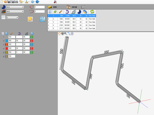
The Linear Advanced Designer allows parts to be created in full 3D. Parts are designed by choosing the number of bends and supplying length, rotation, and angle values. The way the dimensions are placed on either side of each bend can be customized as well.
A tutorial on how to create a part using this designer is available here: Linear Advanced Designer Tutorial
How To
Start Up
To access this designer, click the linear advanced button ![]() . This will open a new, blank part design.
. This will open a new, blank part design.
Part Design
Once a new linear advanced part design window has been opened, a new part can be created.
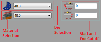
First, a die and material should be chosen. This can be done by clicking on the drop down menus next to the die and material icons in the top left corner of the screen.If any cut-off is necessary, enter the amount needed into the start and end cut-off fields. The first/top field represents the cut-off at the start of the part and the second/bottom field represents the cut-off at the end of the part.
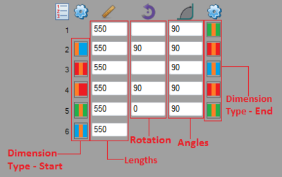
To start designing the part, enter values into the designer entry fields on the left panel. Each bend and the last straight length will have its own row. The first column represents the dimension type for the start of the dimension. The second column below the ruler icon represents the straight lengths of tube. The third column below the arrow icon represents the rotations for each bend. The fourth column below the angle icon represents the angle of each bend. The fifth column represents the dimension type for the end of the dimension. See image below.
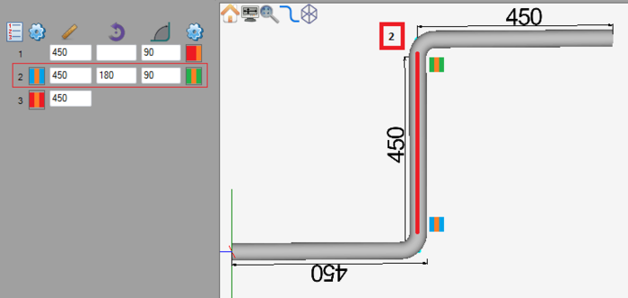
For example, on the second bend, the first column of dimension types will affect the dimension on the far end of the bend and the second dimension column will affect the end closest to the bend. See image below.
Dimension Types
 Outside Perpendicular: The dimension goes along the tube to the perpendicular point on the outside of the bend. (Note: Should be used on bends of 90° or greater for it to have an effect.)
 Center-line Perpendicular: The dimension goes along the tube to the perpendicular point in the center of the bend. (Note: Should be used on bends of 90° or greater for it to have an effect.)
 Inside Perpendicular: The dimension goes along the tube to the perpendicular point on the inside of the bend. (Note: Should be used on bends of 90° or greater for it to have an effect.)
Controls and Options
Notes can be attached to the part design project using the note button ![]() . Notes are saved with the part and are included on the part's setup sheet.
. Notes are saved with the part and are included on the part's setup sheet.
The auto-zoom option can be turned on or off using the auto-zoom button (On) ![]() / (Off)
/ (Off) ![]() . When activated, auto-zoom will zoom in or out to accommodate the size of the part. For example, if a length is originally 200 and is changed to 2000, it may extend past the part display's extend. Auto-zoom will zoom out to make sure the whole part is visible.
. When activated, auto-zoom will zoom in or out to accommodate the size of the part. For example, if a length is originally 200 and is changed to 2000, it may extend past the part display's extend. Auto-zoom will zoom out to make sure the whole part is visible.
