Linear Advanced Designer Tutorial
Contents
Introduction
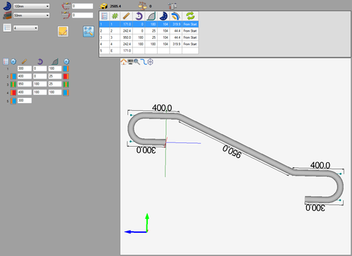
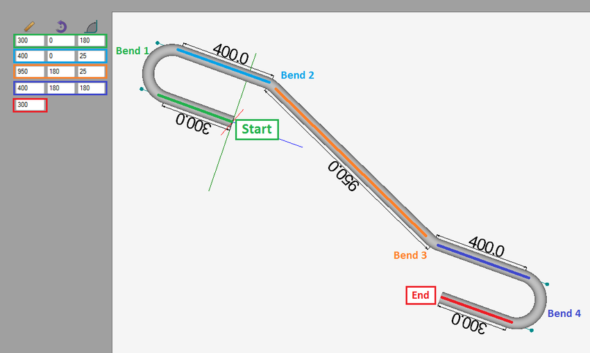
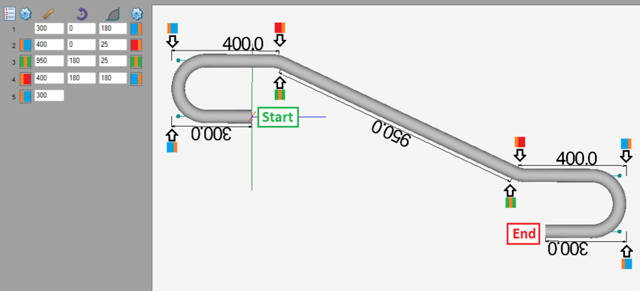
This tutorial will step through the process of of creating a part (Shown on the right) in the linear advanced designer interface.While designing in the linear advanced designer, the die, material, number of bends, and lengths, rotations, and angles are provided to determine the shape of the part. The location of the dimensions on either side of each bend can also be customized.
Note: This tutorial will use millimeters as the measurement units.
Tutorial
Step 1
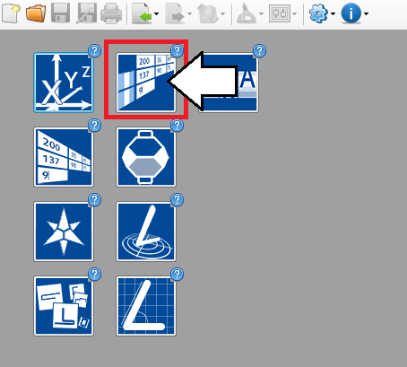
First, a new linear advanced part design needs to be started. On the start up page, click the Linear Advanced Designer button. ![]()
Step 2
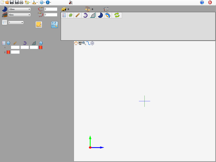
Now a new linear advanced part design window will open. This is where the part will be designed.
Step 3
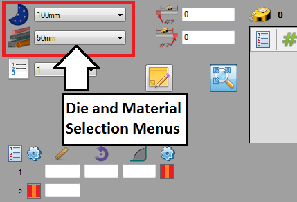
First of all, the die and material need to to be chosen. The die and material menus are located in the upper left corner of the designer window.
Choose a die by clicking the drop down menu next to the die icon. Select the 100mm die from the list, as shown in the image below. (Note: This die was made in the Die Library Tutorial. If this die is not shown in the die selection menu, please complete the die library tutorial before proceeding.)
Choose a material by clicking the drop down menu next to the material icon. Select the 50mm material from the list, as shown in the image below. (Note: This material was made in the Material Library Tutorial. If this material is not shown in the material selection menu, please complete the material library tutorial before proceeding.)
Step 4
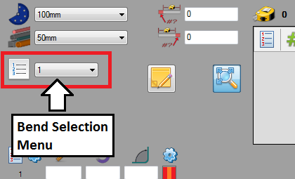
Next, the number of bends in the part will be selected. The bend selection menu is located in the upper left corner just below the die and material menus. The part that will be created in this tutorial is going to have 4 bends.
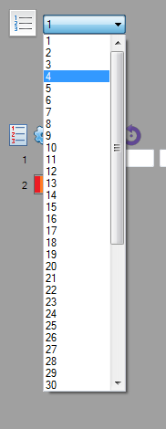
Choose the amount of bends by clicking the drop down menu next to the bend number icon. Select the number 4 from the list as shown in the image below. Once the number of bends has been increased to 4, the coordinate fields will adjust accordingly. There will be 5 rows available now.
Step 6
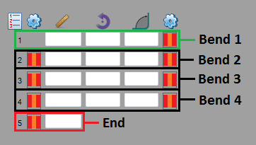
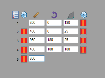
In the coordinate entry fields on the left side of the window, there will be 5 rows and 3 columns. The first 4 rows will represent the length, rotation, and angle of each bend (Row 1 defines bend 1, Row 2 defines bend 2, etc.). The 5th row will be the length of the last length on the part.
The first column of fields represents the length before the bend, the middle column represents the rotation, and the third column represents the angle of the bend.
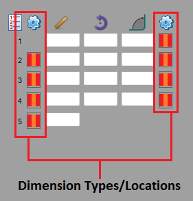
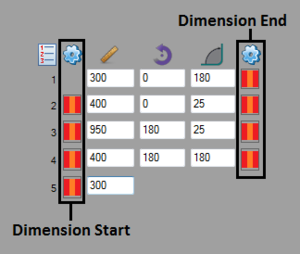
On either side of the entry fields, there will be columns of red and orange striped icons. These icons will be changed to modify the dimension locations on either side of each bend.
Step 7
Now the coordinates will be entered. These coordinates will define the shape of the part.
Enter the exact coordinates shown in the image below. Ignore the dimension types alone for now. They will be dealt with in the next step.
Tip: Hitting the tab key will move the cursor to the next available cell while entering the coordinates.
Each set of coordinates represents a specific length and bend on the part, as shown below.
Step 8
Next, the dimension locations will be adjusted.
The dimension locations/types are represented by the icons on either side of the entry fields. The column of icons on the left side are the locations for the start of each dimension and the icons on the right side are the locations for the ends of each dimension.
There are seven different dimension types available. For information on each type, see the dimension types section on the Linear Advanced Designer Quick Start page.
Dimension types are changed by clicking the dimension icon and selecting an option from the menu that appears.
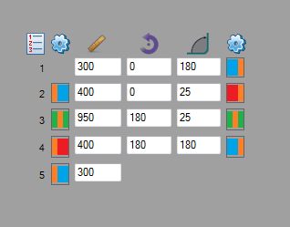
For this part, select the dimension types as shown below:
Dimension number...
1.) End: ![]() Outside Perpendicular
Outside Perpendicular
2.) Start: ![]() Outside Perpendicular, End:
Outside Perpendicular, End: ![]() Outside Apex
Outside Apex
3.) Start: ![]() Tangent, End:
Tangent, End: ![]() Tangent
Tangent
4.) Start: ![]() Outside Apex, End:
Outside Apex, End: ![]() Outside Perpendicular
Outside Perpendicular
5.) Start: ![]() Outside Perpendicular
Outside Perpendicular
Once the dimensions types are chosen, make sure the icons look just like the image below.
See image below for an explanation of how each dimension will look after the type is modified.
Step 9
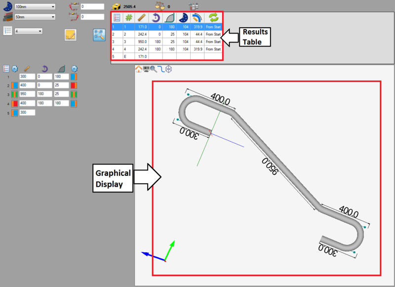
As each set of coordinate values are supplied, the 3D part model will be generated in the graphical display to the right. Once all coordinates are entered, the complete part will be shown. The part's bend information will also be generated in the results table at the top of the window. See the image below.
Depending on the options chosen in the results/output format and results/output settings tabs in the program settings menu, the results table may look slightly different.
Step 10
The part is now complete!
The part design file can be saved by going up to the main tool bar and clicking the save option. ![]()
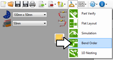
The bend order can also be adjusted in the bend order menu.
The part setup sheet can also be printed by clicking the print option on the main tool bar. ![]()
