Die Library Tutorial
Introduction
This tutorial will step through the process of creating and adding a die to the die library. The units used throughout this tutorial will be millimeters.
Note that this will cover the very basics of this process. When adding a die that will actually be used to bend parts, there may be more details that will need to be added.
Tutorial
Step 1
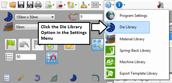
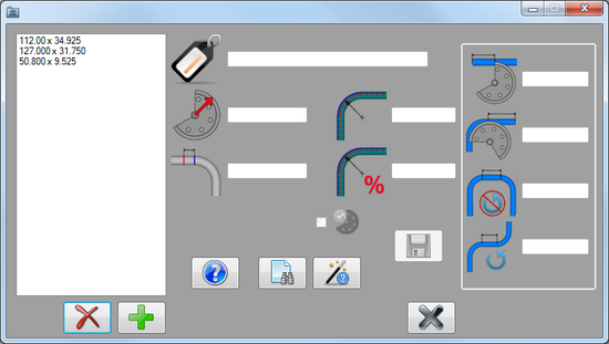
First, the die library needs to be opened. Go to the main tool bar at the top of the window and click the settings menu. From the drop down menu, click the die library option, as seen in the image to the right. The die library window will open as shown below.
Step 2
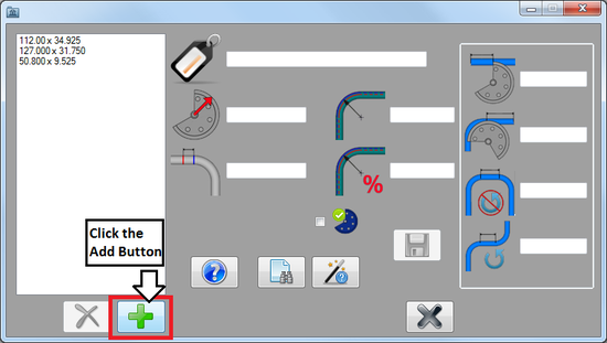
Now that the die library is opened, a die can be added. To do so, first click the add button ![]() below the die list.
below the die list.
Step 3
Once the add button has been clicked, the attribute fields to the right will be open to type in.
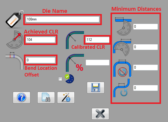
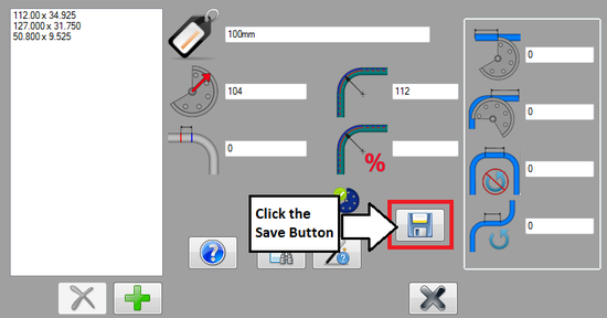
Fill in the fields with the information as shown below.
- Name: The name given here will be what the die is called everywhere in the software. For example, in the main die selection menu in any of the part designers. This die is given the name 100mm referring to it's stamped CLR value.
- Achieved CLR: The achieved CLR is the CLR that the die will actually produce when bending. This value compensates for spring-back and other factors that contribute to inaccuracies in the CLR of a bend. In this case, 4% was added to the stamped CLR, resulting in 104.
- Calibrated CLR: The calibrated CLR is a value based on specific measurements of a bend created by the die and used by the software to ensure accuracy. In this case, to keep things simple, 12% of the stamped CLR was added which results in 112.
- In any other situation, the die calibration wizard should be used to calculate this value. The dies in the OEM die list also have this value included in their predefined attributes.
- Note: For the sake of simplicity, the bend location offset and the minimum distance values were set to 0. As this die will not actually be used to bend any parts and will strictly be used for tutorial purposes, so these values aren't essential. The K factor was also left blank since the calibrated CLR is being used instead.
Step 4
Once all the die attributes have been entered correctly, the die can be saved and added to the die library.
To add the die, click the save button ![]() below the attribute fields.
below the attribute fields.
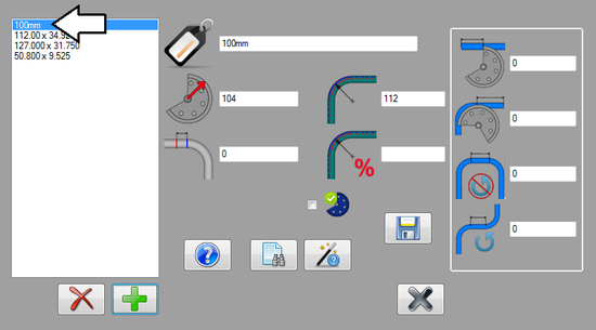
After saved is clicked, the die will appear in the die list to the left.
Step 5
The die has been successfully added to the die library!
