Difference between revisions of "Graphical Display"
| (11 intermediate revisions by the same user not shown) | |||
| Line 1: | Line 1: | ||
==Description== | ==Description== | ||
| − | [[File:graph01.png|right|400px]]In each designer, a model of the part will be generated in the graphical/part display to the right of the design panel. | + | [[File:graph01.png|right|400px]]In each designer, a 3D model of the part will be generated in the graphical/part display to the right of the design panel. |
| Line 25: | Line 25: | ||
===Display Control Icons=== | ===Display Control Icons=== | ||
| + | The display control icons are located in the upper left corner of the graphical display. | ||
[[File:graph02.png]] | [[File:graph02.png]] | ||
| Line 31: | Line 32: | ||
*'''Reset View:''' Click the reset view/house icon to set the part orientation back to the default view. This will bring the part model back to how it was displayed before any view adjustments were made. | *'''Reset View:''' Click the reset view/house icon to set the part orientation back to the default view. This will bring the part model back to how it was displayed before any view adjustments were made. | ||
| + | :[[File:graph04.png|800px]] | ||
| − | |||
| − | *''' | + | *'''Center View:''' Click the center view icon to bring the currently selected bend tool to the center of the graphical display. This will bring the selected design tool to the center of the screen and zoom in while maintaining the current part rotation. |
| + | :'''''Note:''''' ''This feature should be used with the [[Grapple Designer|grapple]] and [[Harpoon Designer|harpoon]] designer interfaces. Outside of these designers, this feature will function the same as zoom fit.'' | ||
| − | + | :[[File:graph05.png|800px]] | |
| − | :''' | + | |
| + | |||
| + | *'''Zoom Fit:''' Click the zoom fit icon to zoom all the way in on the part model and fit it to the graphical display frame while maintaining the part's rotation. | ||
| + | |||
| + | :[[File:graph06.png|800px]] | ||
| + | |||
| + | |||
| + | |||
| + | *'''Toggle Part Display:''' Click the toggle part display icon to turn on or off the part dimension markers and values, apex guides, axis on the part, directional axis in the bottom left corner, and design rings/tools (If using [[Linear Dynamic Designer|linear dynamic designer]]). See image below for an example. | ||
| + | |||
| + | :'''''Note:''''' ''If the program settings [[Program Settings#Defaults Tab|display dimensions]] option is turned off or the [[Machine Library|machine]] that is currently in use has the [[Machine Library#Defaults Tab|display dimensions]] option turned off, the toggle part display icon will not affect the dimensions on the part model. | ||
:[[File:graph03.png|800px]] | :[[File:graph03.png|800px]] | ||
| Line 46: | Line 58: | ||
| − | |||
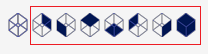
| + | *'''Select View:''' [[File:graph07.png|right]]The select view icon allows the part to be viewed from a specific direction. '''To choose a new viewing direction''', click the select view icon. Once clicked, a set of icons will appear next to the select view icon, as shown to the right. Each represents a different direction. Click on any of these icons to view the part from the direction specified by the icon. | ||
| + | |||
| + | :[[File:graph08.png|700px]] | ||
===Pan/Move=== | ===Pan/Move=== | ||
| + | To '''pan/move''' the part model around the graphical display frame, use any of the following methods: | ||
| + | |||
| + | '''1.)''' Click and hold both mouse buttons and move the cursor around the frame. The part will follow the cursor's movements. | ||
| + | |||
| + | :'''Or...''' | ||
| + | |||
| + | '''2.)''' [[File:keyboard.png|right|350px]]Use the num keys (''See image to the right'') on the keyboard to nudge the part model. | ||
| + | |||
| + | ::*'''Pan Up''' --> Num 8 | ||
| + | ::*'''Pan Down''' --> Num 2 | ||
| + | ::*'''Pan Left''' --> Num 4 | ||
| + | ::*'''Pan Right''' --> Num 6 | ||
| + | |||
| + | |||
| + | |||
| + | |||
| + | |||
| + | ===Zoom=== | ||
| + | To '''zoom in or out''', use any of the following methods: | ||
| + | |||
| + | '''1.)''' Use the mouse scroll wheel. Scroll up to zoom out and scroll down to zoom in. ('''''Note:''''' ''This can be reversed using the [[Program Settings#Default Tab|invert zoom]] option in the program settings menu.'') | ||
| + | |||
| + | :'''Or...''' | ||
| + | |||
| + | '''2.)''' [[File:keyboard2.png|right|350px]]Use the '''plus [+]''' or '''minus [-]''' keys on the keyboard. Press '''plus [+]''' to zoom in and press '''minus [-]''' to zoom out. | ||
| + | |||
| + | |||
| + | |||
| + | |||
| + | |||
| + | |||
| + | |||
===Rotate=== | ===Rotate=== | ||
| + | To '''rotate''' the part model, use any of the following methods: | ||
| + | '''1.)''' Click and hold the right mouse button and move the cursor around to rotate the part model. | ||
| − | + | :'''Or...''' | |
| + | |||
| + | '''2.)''' Press the spacebar on the keyboard to enter rotate mode. Once in rotate mode, move the mouse around to rotate the part. To exit rotate mode, either hit the spacebar again or click the right mouse button. | ||
Latest revision as of 13:31, 19 August 2013
Description

The view of the part model can be controlled by moving, rotating, zooming, and/or using the display icons.
How To
Display Control Icons
The display control icons are located in the upper left corner of the graphical display.

- Reset View: Click the reset view/house icon to set the part orientation back to the default view. This will bring the part model back to how it was displayed before any view adjustments were made.

- Center View: Click the center view icon to bring the currently selected bend tool to the center of the graphical display. This will bring the selected design tool to the center of the screen and zoom in while maintaining the current part rotation.
- Note: This feature should be used with the grapple and harpoon designer interfaces. Outside of these designers, this feature will function the same as zoom fit.

- Zoom Fit: Click the zoom fit icon to zoom all the way in on the part model and fit it to the graphical display frame while maintaining the part's rotation.

- Toggle Part Display: Click the toggle part display icon to turn on or off the part dimension markers and values, apex guides, axis on the part, directional axis in the bottom left corner, and design rings/tools (If using linear dynamic designer). See image below for an example.
- Note: If the program settings display dimensions option is turned off or the machine that is currently in use has the display dimensions option turned off, the toggle part display icon will not affect the dimensions on the part model.

- Select View: The select view icon allows the part to be viewed from a specific direction. To choose a new viewing direction, click the select view icon. Once clicked, a set of icons will appear next to the select view icon, as shown to the right. Each represents a different direction. Click on any of these icons to view the part from the direction specified by the icon.


Pan/Move
To pan/move the part model around the graphical display frame, use any of the following methods:
1.) Click and hold both mouse buttons and move the cursor around the frame. The part will follow the cursor's movements.
- Or...

- Pan Up --> Num 8
- Pan Down --> Num 2
- Pan Left --> Num 4
- Pan Right --> Num 6
Zoom
To zoom in or out, use any of the following methods:
1.) Use the mouse scroll wheel. Scroll up to zoom out and scroll down to zoom in. (Note: This can be reversed using the invert zoom option in the program settings menu.)
- Or...

Rotate
To rotate the part model, use any of the following methods:
1.) Click and hold the right mouse button and move the cursor around to rotate the part model.
- Or...
2.) Press the spacebar on the keyboard to enter rotate mode. Once in rotate mode, move the mouse around to rotate the part. To exit rotate mode, either hit the spacebar again or click the right mouse button.