Harpoon Designer
Description
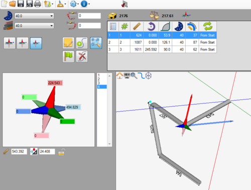
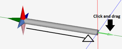
The Harpoon Designer allows parts to be created in full 3D. Parts are designed by clicking and dragging the tube out from a harpoon style axis.
A tutorial on how to create a part using this designer is available here: Harpoon Designer Tutorial
How To
Start Up
To access this designer, click the harpoon button ![]() on the start up page. This will open a new, blank part design.
on the start up page. This will open a new, blank part design.
Part Design
Once a new harpoon part design window has been opened, a new part can be created.
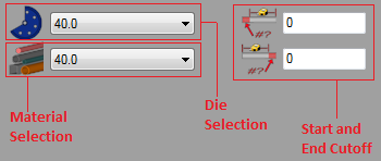
First, a die and material should be chosen. This can be done by clicking on the drop down menus next to the die and material icons in the top left corner of the screen.
If any cut-off is necessary, enter the amount needed into the start and end cut-off fields. The first/top field represents the cut-off at the start of the part and the second/bottom field represents the cut-off at the end of the part.
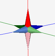
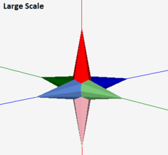
The harpoon has six different direction points. Each will pull the current straight length of the part in the chosen direction.
Note: A single straight length can be dragged in 3 total directions. For example, if the darker green harpoon point is dragged out, the light green arrow cannot be pulled. In the designer entry fields, if the light blue field has a value of 500, it will be set to 0 if any values are entered in the darker blue field.
In summary, part designs can be edited using 3 different methods:
1.) By selecting a harpoon point and dragging it into place.
2.) By selecting a harpoon point and keying in the value.
3.) By entering values directly into the fields on the left of the screen.
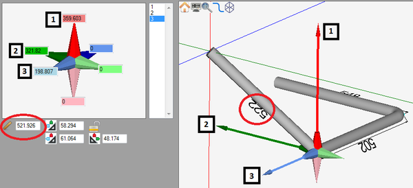
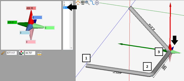
As the part is being drawn, the lengths, angles and rotations will be automatically generated in the designer entry fields on the left of the screen. The value next to the ruler icon represents the length of the straight section before the currently selected bend. The values in the colored fields in the harpoon frame show how far and in which direction the current length of tube has been moved. Any of these values can be edited by typing in new values. See below for an example.
To remove the last bend, click the delete bend button ![]() .
.
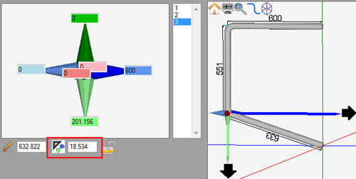
Once more than one angle is applied to a bend (Example: Pulled the light green harpoon point and then pulled the red harpoon point), the angle as well as the axis that the angle is along will be shown below the value fields in the left panel next to an axis icon. The colors of the small arrows on this icon correspond to the axes that the angle is along. These angle values can be also edited by entering values directly into the given fields.
If more than two angles are added to the bend, two more angle values will be generated. These will also have axis icons that will show which axes the angles are along. These can also be edited by directly entering values into the fields.
Individual bends' angles can be locked by clicking on and toggling the lock icon on or off. When a bend is locked, the angles of the bend will be locked in place if any attempts to change them are made. While locked, dragging the harpoon points will only adjust the length of the straight after the bend.
Controls and Options
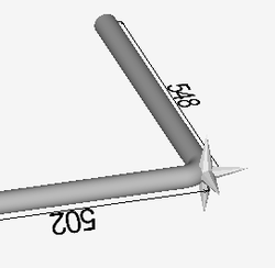
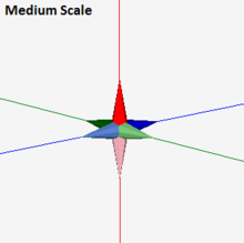
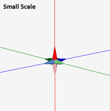
To adjust the scale at which the part is being viewed in the part display, click either the large, medium, or small scale buttons. See images below for an explanation of each scale.
Notes can be attached to the part design project using the note button ![]() . Notes are saved with the part and are included on the part's setup sheet.
. Notes are saved with the part and are included on the part's setup sheet.
To add another bend to the part, click the add bend button ![]() .
.
The auto-zoom option can be turned on or off using the auto-zoom button (On) ![]() / (Off)
/ (Off) ![]() . When activated, auto-zoom will zoom in or out to accommodate the size of the part. For example, if a length is originally 200 and is changed to 2000, it may extend past the part display's extend. Auto-zoom will zoom out to make sure the whole part is visible.
. When activated, auto-zoom will zoom in or out to accommodate the size of the part. For example, if a length is originally 200 and is changed to 2000, it may extend past the part display's extend. Auto-zoom will zoom out to make sure the whole part is visible.
To completely start over and delete the whole part design, click the start over button ![]() .
.
To delete the last bend that was added to the part, click the delete bend button ![]() .
.
