Difference between revisions of "Linear 2D Designer Tutorial"
| Line 82: | Line 82: | ||
Now the first length of the part will be defined. First, '''click the center of the blue and green axis''' in the graphical display. This will be the starting point of the part. | Now the first length of the part will be defined. First, '''click the center of the blue and green axis''' in the graphical display. This will be the starting point of the part. | ||
| − | Once clicked, a light blue line will extend from this point | + | Once clicked, a light blue line will extend from this point that will connect to the cursor and snap to the grid. This line will be used as a reference line to draw out each length of the part. |
Next, '''click the point 400 mm to the right'''. This will be the end of the first length of the part. Once this second point is clicked, the length will be shown in the chosen material. | Next, '''click the point 400 mm to the right'''. This will be the end of the first length of the part. Once this second point is clicked, the length will be shown in the chosen material. | ||
| Line 107: | Line 107: | ||
==='''Step 7'''=== | ==='''Step 7'''=== | ||
| + | Now the next length of the part will be added to the part. | ||
| + | |||
| + | '''Click the point 300 mm down and 300 mm to the right'''. | ||
| + | |||
| + | [[File:lin2dtut14.png|1050px]] | ||
| + | |||
| + | |||
| + | |||
| + | |||
| + | |||
| + | ==='''Step 8'''=== | ||
| + | (L 4) | ||
| + | |||
| + | |||
| + | ==='''Step 9'''=== | ||
| + | (L 5) | ||
| + | |||
| + | |||
| + | ==='''Step 10'''=== | ||
| + | (L 6) | ||
| + | |||
| + | |||
| + | ==='''Step 11'''=== | ||
| + | (coord explanation) | ||
| + | |||
| + | |||
| + | ==='''Step 12'''=== | ||
| + | (results and graph) | ||
| + | |||
| + | |||
| + | ==='''Step 13'''=== | ||
| + | (complete) | ||
Revision as of 09:13, 1 July 2013
Contents
Introduction
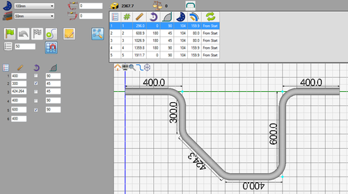
This tutorial will step through the process of of creating a part (Shown to the right) in the linear 2D designer interface.While designing in the linear 2D designer, the die, material, and each straight length is drawn out to determine the shape of the part.
Note: This tutorial will use millimeters as the measurement units.
Tutorial
Step 1
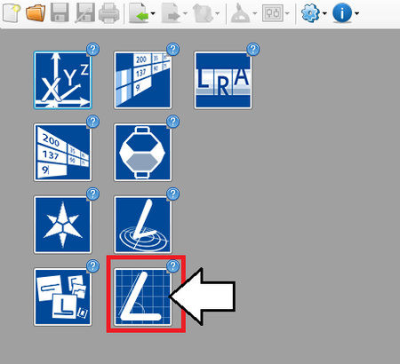
First, a new Linear 2D part design needs to be started. On the start up page, click the Linear 2D Designer button. 
Note: Depending on the version of software currently in use, fewer designer buttons may be included on the start up page.
Step 2
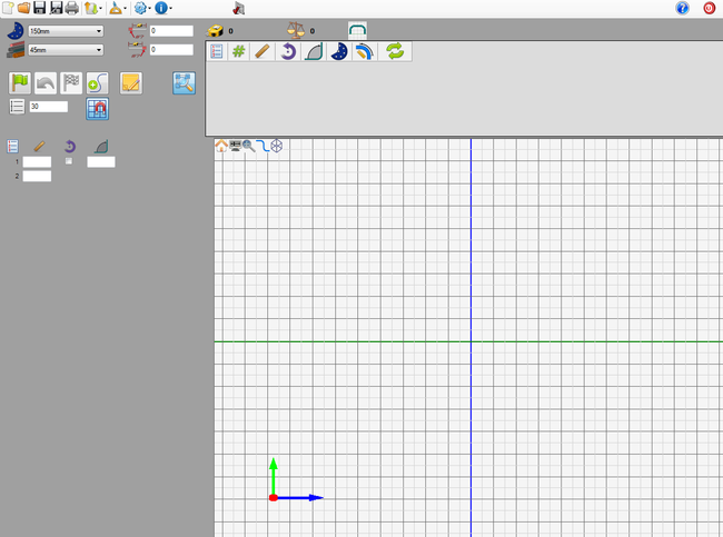
Now a new Linear 2D part designer window will open. This is where the part will be designed.
Step 3
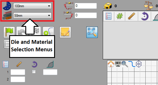
First of all, the die and material need to to be chosen. The die and material menus are located in the upper left corner of the designer window.
Choose a die by clicking the drop down menu next to the die icon. Select the 100mm die from the list, as shown in the image below. (Note: This die was made in the Die Library Tutorial. If this die is not shown in the die selection menu, please complete the die library tutorial before proceeding.)
Choose a material by clicking the drop down menu next to the material icon. Select the 50mm material from the list, as shown in the image below. (Note: This material was made in the Material Library Tutorial. If this material is not shown in the material selection menu, please complete the material library tutorial before proceeding.)
Step 4
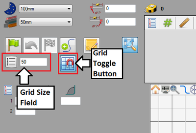
Next, the grid will be adjusted. The grid is displayed on the graphical display to the right. The grid options are located just above the entry fields, as shown to the right.First, make sure the grid is turned on. If the grid is off, click the grid button ![]() to activate it.
to activate it.
Next, the size of the grid cells will be changed. The size of each cell is determined by the value given in the grid size field. Enter 50 into this field to change the cell size.
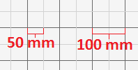
Each of the smallest grid cells (grey lines) are 50 mm and each of the larger grid cells (darker lines) are 100 mm. See image below.
Step 5
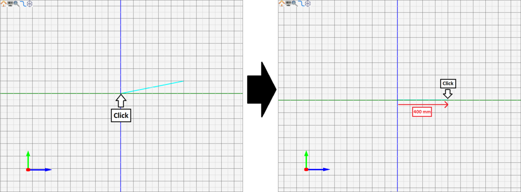
Now the first length of the part will be defined. First, click the center of the blue and green axis in the graphical display. This will be the starting point of the part.
Once clicked, a light blue line will extend from this point that will connect to the cursor and snap to the grid. This line will be used as a reference line to draw out each length of the part.
Next, click the point 400 mm to the right. This will be the end of the first length of the part. Once this second point is clicked, the length will be shown in the chosen material.
Step 6
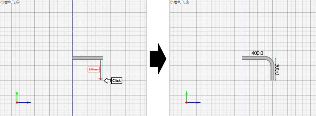
After the first length of the part is drawn, the light blue line will be connected to the end point of the first length. Now the next section of the part will be drawn.
Click the point 300 mm down from the last point. The first length, first bend, and second length have now been designed. Notice how the dimensions are generated on the part after the second length is added.
Step 7
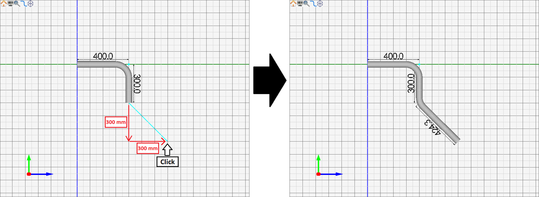
Now the next length of the part will be added to the part.
Click the point 300 mm down and 300 mm to the right.
Step 8
(L 4)
Step 9
(L 5)
Step 10
(L 6)
Step 11
(coord explanation)
Step 12
(results and graph)
Step 13
(complete)
