Difference between revisions of "Grapple Designer Tutorial"
| (9 intermediate revisions by the same user not shown) | |||
| Line 4: | Line 4: | ||
| − | While designing a part in the grapple designer, the die and material are chosen and the part is designed by clicking and dragging the grapple tool. | + | While designing a part in the grapple designer, the die and material are chosen and the part is designed by clicking and dragging the grapple tool and/or entering values into the entry fields. |
| Line 29: | Line 29: | ||
==='''Step 1'''=== | ==='''Step 1'''=== | ||
| − | First, a '''new grapple part design''' needs to be started. On the start up page, click the '''grapple designer''' button. [[File: | + | First, a '''new grapple part design''' needs to be started. On the start up page, click the '''grapple designer''' button. [[File:grappicon.png]] |
'''''Note:''''' ''Depending on the version of software currently in use, fewer designer buttons may be included on the start up page.'' | '''''Note:''''' ''Depending on the version of software currently in use, fewer designer buttons may be included on the start up page.'' | ||
| − | [[File:grapptut2.png | + | [[File:grapptut2.png]] |
| Line 48: | Line 48: | ||
==='''Step 3'''=== | ==='''Step 3'''=== | ||
| + | [[File:grapptut6.png|right|460px]]First of all, '''the die and material need to to be chosen'''. The die and material menus are located in the upper left corner of the designer window. | ||
| + | |||
| + | |||
| + | '''Choose a die''' by clicking the drop down menu next to the die icon. '''Select the 100mm die''' from the list, as shown in the image below. ('''''Note:''''' ''This die was made in the [[Die Library Tutorial]]. If this die is not shown in the die selection menu, please complete the die library tutorial before proceeding.'') | ||
| + | |||
| + | [[File:temptut8.png]] | ||
| + | |||
| + | |||
| + | '''Choose a material''' by clicking the drop down menu next to the material icon. '''Select the 50mm material''' from the list, as shown in the image below. ('''''Note:''''' ''This material was made in the [[Material Library Tutorial]]. If this material is not shown in the material selection menu, please complete the material library tutorial before proceeding.'') | ||
| + | |||
| + | [[File:temptut9.png]] | ||
| + | |||
| + | |||
| + | |||
| + | |||
| + | |||
| + | |||
| + | ==='''Step 4'''=== | ||
| + | Directly below the die and material menus, there are '''three preset scale buttons''' that can be used to control the zoom level of the graphical/part model display. '''Click the medium scale''' button (in the middle). | ||
| + | |||
| + | [[File:grapptut7.png|450px]] | ||
| + | |||
| + | |||
| + | |||
| + | |||
| + | ==='''Step 5'''=== | ||
| + | Now the first length of the part will be created. '''Click and drag the light green grapple handle until it is 500 mm'''. Watch the '''light green entry field or the length field''' to keep track of the length. | ||
| + | |||
| + | |||
| + | '''''Tip:''''' While manually dragging the part length is convenient, it can be a bit tricky to get exact measurements. To define a part length you can also use any of these other methods: | ||
| + | |||
| + | '''''1.''''' Type the length into the entry field that matches the grapple handle (In this case, the light green entry field). | ||
| + | |||
| + | '''''2.''''' Click the grapple handle (In this case, the light green handle) and directly type in the length using the keyboard. | ||
| + | |||
| + | |||
| + | [[File:grapptut8.png|700px]] | ||
| + | |||
| + | |||
| + | |||
| + | |||
| + | ==='''Step 6'''=== | ||
| + | [[File:grapptut9.png|right|450px]]Next, the '''first bend will be added to the part'''. '''Click the add bend''' button. [[File:addbend.png]] | ||
| + | |||
| + | The add bend button is located near the upper left corner, as shown in the image to the right. Once this button is clicked, a bend will be added to the part. | ||
| + | |||
| + | |||
| + | |||
| + | In the '''bend list''' below, there will be a '''1''' and a '''2''' listed. The '''1 represents the length that was added in step 5''' and the '''2 represents the bend/length''' that will be created in this step. | ||
| + | |||
| + | [[File:grapptut10.png|400px]] | ||
| + | |||
| + | |||
| + | On the '''part model in the graphical display''', the main axis will move to the end of the part. See image below. | ||
| + | |||
| + | [[File:grapptut11.png|500px]] | ||
| + | |||
| + | |||
| + | |||
| + | '''Click and drag the dark blue grapple handle''' until the new length is around '''550 mm'''. Watch the dark blue entry field, the length field, or the part dimension to get the length measurement. ('''''Alternatives:''''' ''Type the length into the entry field, click the grapple handle and directly type in the length, or click & drag the grapple handle then enter the length into the length field.'') | ||
| + | |||
| + | [[File:grapptut12.png|700px]] | ||
| + | |||
| + | |||
| + | |||
| + | |||
| + | |||
| + | |||
| + | ==='''Step 7'''=== | ||
| + | Now, the '''second bend''' will be added to the part. Click the '''add bend''' button. [[File:addbend.png]] | ||
| + | |||
| + | |||
| + | On the '''part model in the graphical display''', the main axis will be moved to the end of the part and another bend ('''3''') will be added to the '''bend list''', as shown below. | ||
| + | |||
| + | [[File:grapptut13.png|650px]] | ||
| + | |||
| + | |||
| + | First, '''click and drag the red grapple handle up to about 590 mm'''. Watch the red entry field, the length field, and/or the part dimension to keep track of the length. ('''''Alternatives:''''' ''Type the length into the entry field, click the grapple handle and directly type in the length, or click & drag the grapple handle then enter the length into the length field.'') | ||
| + | |||
| + | [[File:grapptut14.png|700px]] | ||
| + | |||
| + | |||
| + | |||
| + | Now the '''angle of this bend will be adjusted''' by pulling the length in another direction. '''Click and drag the light blue grapple handle about 378 mm''' and until the '''total length of this section is just about 700.7 mm'''. ('''''Alternatives:''''' ''Type the length into the entry field or click the grapple handle and directly type in the length.'') | ||
| + | |||
| + | [[File:grapptut15.png|700px]] | ||
| + | |||
| + | |||
| + | After the light blue handle is pulled, a '''new field will have appeared below the entry fields area''', as shown below. This is the '''angle field'''. The icon next to this field will show which axis the angle is along. In this case, the value here represents the angle along the red and light blue axis. The angle should be close to '''57.3'''. | ||
| + | |||
| + | [[File:grapptut16.png|350px]] | ||
| + | |||
| + | |||
| + | |||
| + | |||
| + | |||
| + | ==='''Step 8'''=== | ||
| + | Now, the '''third bend''' will be created. Click the '''add bend''' button. [[File:addbend.png]] | ||
| + | |||
| + | On the '''part model in the graphical display''', the main axis will be moved to the end of the part and another bend ('''4''') will be added to the '''bend list''', as shown below. | ||
| + | |||
| + | [[File:grapptut17.png|700px]] | ||
| + | |||
| + | |||
| + | '''Click and drag the dark blue grapple handle''' until the length measures roughly '''770 mm'''. ('''''Alternatives:''''' ''Type the length into the entry field, click the grapple handle and directly type in the length, or click & drag the grapple handle then enter the length into the length field.'') | ||
| + | |||
| + | [[File:grapptut18.png|700px]] | ||
| + | |||
| + | |||
| + | |||
| + | |||
| + | |||
| + | |||
| + | ==='''Step 9'''=== | ||
| + | Next, the '''fourth bend''' will be created. Click the '''add bend''' button. [[File:addbend.png]] | ||
| + | |||
| + | On the '''part model in the graphical display''', the main axis will be moved to the end of the part and another bend ('''5''') will be added to the '''bend list''', as shown below. | ||
| + | |||
| + | [[File:grapptut19.png|650px]] | ||
| + | |||
| + | |||
| + | |||
| + | '''Click and drag the pink grapple handle''' until the length is around '''550 mm'''. ('''''Alternatives:''''' ''Type the length into the entry field, click the grapple handle and directly type in the length, or click & drag the grapple handle then enter the length into the length field.'') | ||
| + | |||
| + | [[File:grapptut20.png|700px]] | ||
| + | |||
| + | |||
| + | |||
| + | |||
| + | |||
| + | |||
| + | |||
| + | ==='''Step 10'''=== | ||
| + | Lastly, the '''fifth bend''' and the '''end length''' will be added to the part. Click the '''add bend''' button. [[File:addbend.png]] | ||
| + | |||
| + | On the '''part model in the graphical display''', the main axis will be moved to the end of the part and another bend ('''6''') will be added to the '''bend list''', as shown below. | ||
| + | |||
| + | [[File:grapptut21.png|650px]] | ||
| + | |||
| + | |||
| + | |||
| + | '''Click and drag the dark green grapple handle''' until the last length is around '''500 mm'''. It may be helpful to rotate the part to the left so the correct grapple handle can be accessed. ('''''Alternatives:''''' ''Type the length into the entry field, click the grapple handle and directly type in the length, or click & drag the grapple handle then enter the length into the length field.'') | ||
| + | |||
| + | [[File:grapptut22.png|700px]] | ||
| + | |||
| + | |||
| + | |||
| + | |||
| + | |||
| + | |||
| + | ==='''Step 11'''=== | ||
| + | A '''3D model of the part can be viewed in the [[Graphical Display|graphical display]]'''. The part's bend information will also be generated in the '''results table at the top of the window'''. See the image below. | ||
| + | |||
| + | Depending on the options chosen in the [[Program Settings#Results/Output Format|results/output format]] and [[Program Settings#Results/Output Settings|results/output settings]] tabs in the [[Program Settings|program settings menu]], the results table may look slightly different. | ||
| + | |||
| + | |||
| + | [[File:grapptut23.png|700px]] | ||
| + | |||
| + | |||
| + | |||
| + | |||
| + | |||
| + | |||
| + | ==='''Step 12'''=== | ||
| + | '''The part is now complete!''' | ||
| + | |||
| + | |||
| + | The '''part design file can be saved''' by going up to the main tool bar and clicking the '''save''' option. [[File:temptut13.png]] | ||
| + | |||
| + | |||
| + | The '''bend order''' can also be adjusted in the '''[[Bend Order|bend order]]''' menu. | ||
| + | |||
| + | [[File:temptut14.png]] | ||
| + | |||
| + | |||
| + | The '''part setup sheet''' can also be printed by clicking the '''print''' option on the main tool bar. [[File:temptut15.png]] | ||
Latest revision as of 13:45, 19 August 2013
Contents
Introduction
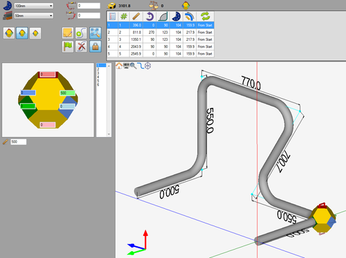
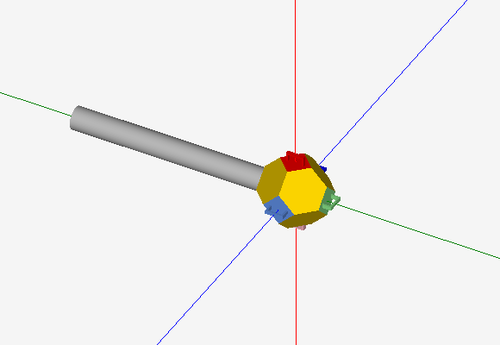
This tutorial will step through the process of designing a part (Shown to the right) in the grapple part designer interface.
While designing a part in the grapple designer, the die and material are chosen and the part is designed by clicking and dragging the grapple tool and/or entering values into the entry fields.
Note: This tutorial will use millimeters as the measurement units.
Tutorial
Step 1
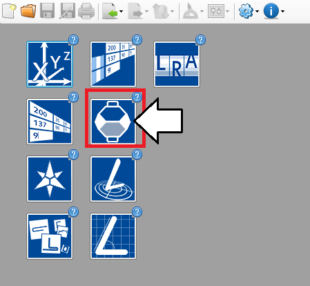
First, a new grapple part design needs to be started. On the start up page, click the grapple designer button. ![]()
Note: Depending on the version of software currently in use, fewer designer buttons may be included on the start up page.
Step 2
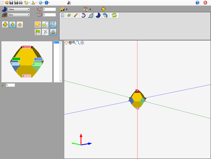
Now a new grapple part designer window will open. This is where the part will be designed.
Step 3
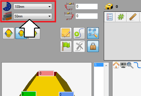
First of all, the die and material need to to be chosen. The die and material menus are located in the upper left corner of the designer window.
Choose a die by clicking the drop down menu next to the die icon. Select the 100mm die from the list, as shown in the image below. (Note: This die was made in the Die Library Tutorial. If this die is not shown in the die selection menu, please complete the die library tutorial before proceeding.)
Choose a material by clicking the drop down menu next to the material icon. Select the 50mm material from the list, as shown in the image below. (Note: This material was made in the Material Library Tutorial. If this material is not shown in the material selection menu, please complete the material library tutorial before proceeding.)
Step 4
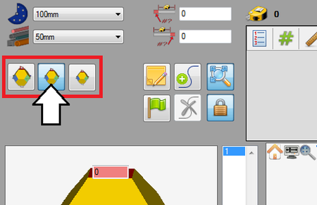
Directly below the die and material menus, there are three preset scale buttons that can be used to control the zoom level of the graphical/part model display. Click the medium scale button (in the middle).
Step 5
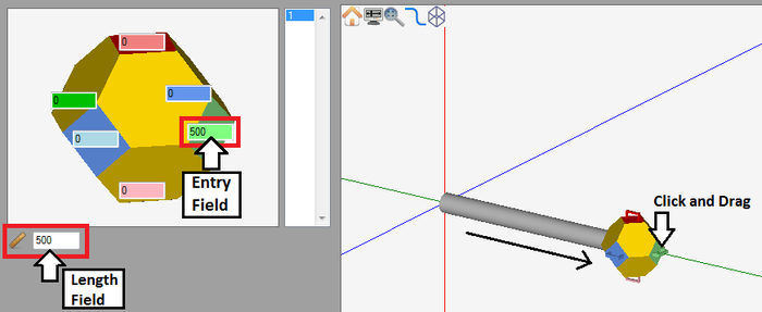
Now the first length of the part will be created. Click and drag the light green grapple handle until it is 500 mm. Watch the light green entry field or the length field to keep track of the length.
Tip: While manually dragging the part length is convenient, it can be a bit tricky to get exact measurements. To define a part length you can also use any of these other methods:
1. Type the length into the entry field that matches the grapple handle (In this case, the light green entry field).
2. Click the grapple handle (In this case, the light green handle) and directly type in the length using the keyboard.
Step 6
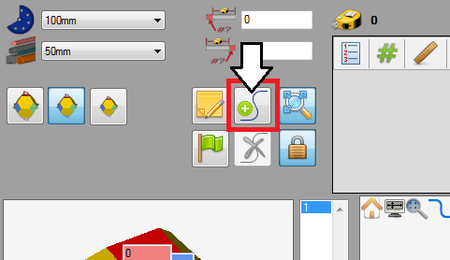
Next, the first bend will be added to the part. Click the add bend button.The add bend button is located near the upper left corner, as shown in the image to the right. Once this button is clicked, a bend will be added to the part.
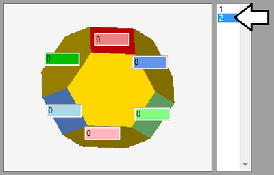
In the bend list below, there will be a 1 and a 2 listed. The 1 represents the length that was added in step 5 and the 2 represents the bend/length that will be created in this step.
On the part model in the graphical display, the main axis will move to the end of the part. See image below.
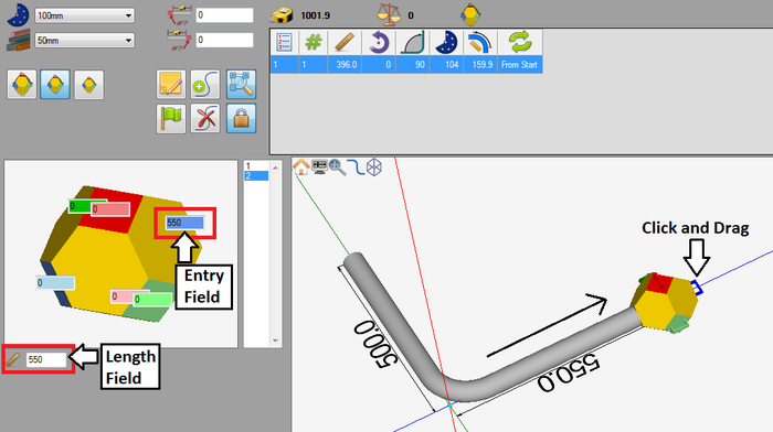
Click and drag the dark blue grapple handle until the new length is around 550 mm. Watch the dark blue entry field, the length field, or the part dimension to get the length measurement. (Alternatives: Type the length into the entry field, click the grapple handle and directly type in the length, or click & drag the grapple handle then enter the length into the length field.)
Step 7
Now, the second bend will be added to the part. Click the add bend button. ![]()
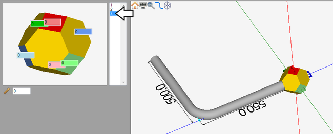
On the part model in the graphical display, the main axis will be moved to the end of the part and another bend (3) will be added to the bend list, as shown below.
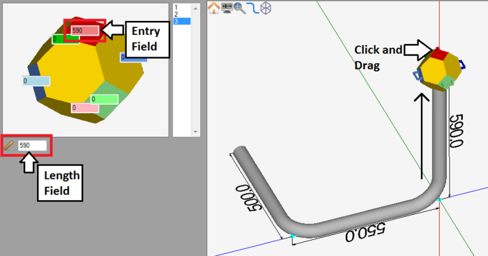
First, click and drag the red grapple handle up to about 590 mm. Watch the red entry field, the length field, and/or the part dimension to keep track of the length. (Alternatives: Type the length into the entry field, click the grapple handle and directly type in the length, or click & drag the grapple handle then enter the length into the length field.)
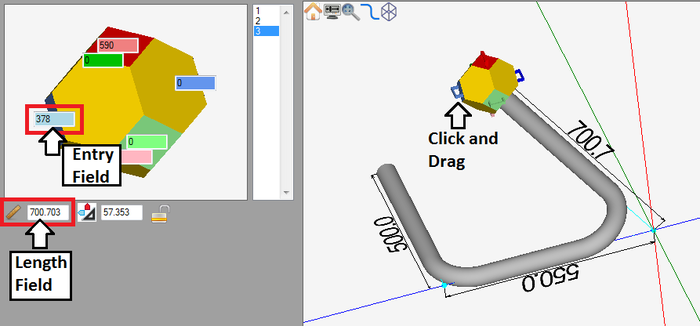
Now the angle of this bend will be adjusted by pulling the length in another direction. Click and drag the light blue grapple handle about 378 mm and until the total length of this section is just about 700.7 mm. (Alternatives: Type the length into the entry field or click the grapple handle and directly type in the length.)
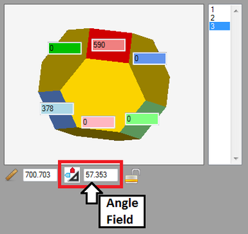
After the light blue handle is pulled, a new field will have appeared below the entry fields area, as shown below. This is the angle field. The icon next to this field will show which axis the angle is along. In this case, the value here represents the angle along the red and light blue axis. The angle should be close to 57.3.
Step 8
Now, the third bend will be created. Click the add bend button. ![]()
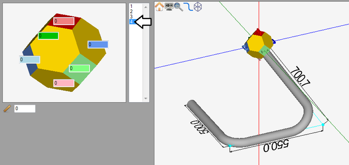
On the part model in the graphical display, the main axis will be moved to the end of the part and another bend (4) will be added to the bend list, as shown below.
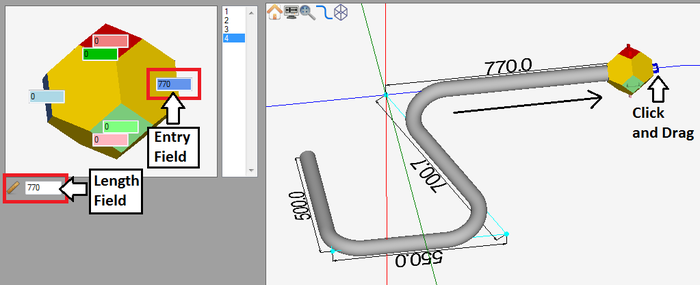
Click and drag the dark blue grapple handle until the length measures roughly 770 mm. (Alternatives: Type the length into the entry field, click the grapple handle and directly type in the length, or click & drag the grapple handle then enter the length into the length field.)
Step 9
Next, the fourth bend will be created. Click the add bend button. ![]()
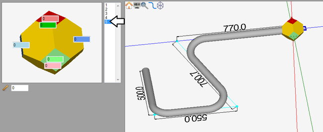
On the part model in the graphical display, the main axis will be moved to the end of the part and another bend (5) will be added to the bend list, as shown below.
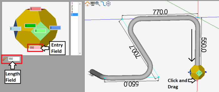
Click and drag the pink grapple handle until the length is around 550 mm. (Alternatives: Type the length into the entry field, click the grapple handle and directly type in the length, or click & drag the grapple handle then enter the length into the length field.)
Step 10
Lastly, the fifth bend and the end length will be added to the part. Click the add bend button. ![]()
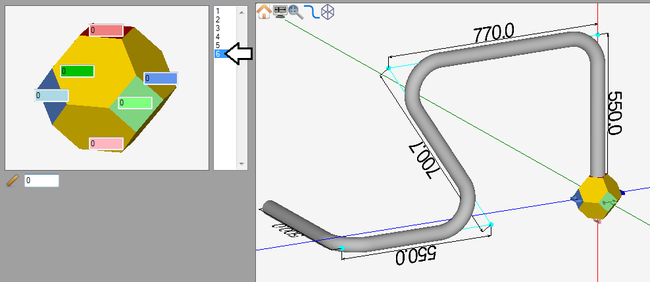
On the part model in the graphical display, the main axis will be moved to the end of the part and another bend (6) will be added to the bend list, as shown below.
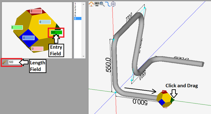
Click and drag the dark green grapple handle until the last length is around 500 mm. It may be helpful to rotate the part to the left so the correct grapple handle can be accessed. (Alternatives: Type the length into the entry field, click the grapple handle and directly type in the length, or click & drag the grapple handle then enter the length into the length field.)
Step 11
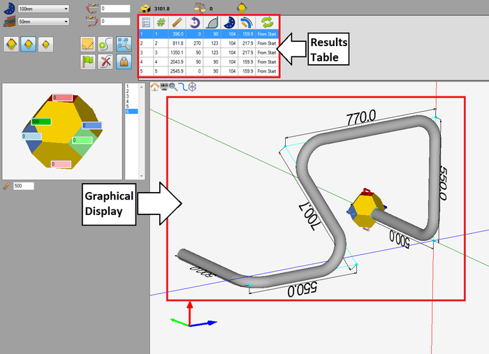
A 3D model of the part can be viewed in the graphical display. The part's bend information will also be generated in the results table at the top of the window. See the image below.
Depending on the options chosen in the results/output format and results/output settings tabs in the program settings menu, the results table may look slightly different.
Step 12
The part is now complete!
The part design file can be saved by going up to the main tool bar and clicking the save option. ![]()
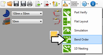
The bend order can also be adjusted in the bend order menu.
The part setup sheet can also be printed by clicking the print option on the main tool bar. ![]()
