Difference between revisions of "Manufacture Checking Tutorial"
| Line 162: | Line 162: | ||
| − | Right now, there is '''only 271 mm of straight material at the end''' of the part. Adding 29 to the end will meet the minimum | + | Right now, there is '''only 271 mm of straight material at the end''' of the part. Adding 29 to the end will meet the minimum requirement. (''In '''[[Manufacture Checking#Step 3|step 3]]''', the minimum length allowed at the end of the part was set to 300.'') |
[[File:mancheck19.png]] | [[File:mancheck19.png]] | ||
| Line 183: | Line 183: | ||
==='''Step 12'''=== | ==='''Step 12'''=== | ||
| − | too short between bends | + | [[File:mancheck22.png|right|500px]]The last problem with the part doesn't have an auto-fix available, so it must be corrected by manually adjusting the part design. The error states that the part is '''58 mm too short between bends.''' |
| + | |||
| + | |||
| + | Right now, there is '''only 42 mm of straight material between the two bends'''. Adding 58 to this length would meet the minimum requirement. (''In '''[[Manufacture Checking#Step 3|step 3]]''', the minimum length allowed between bends without rotation was set to 100.'') | ||
| + | |||
| + | [[File:mancheck23.png]] | ||
| + | |||
| + | |||
| + | '''Close the error chart''' using the exit button in the lower right corner. | ||
| + | |||
| + | [[File:mancheck24.png|450px]] | ||
| + | |||
| + | |||
| + | |||
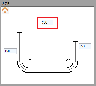
| + | In the entry fields, '''change the upper middle field to 300'''. This will exceed the amount of material required between the bends. Instead of adding just the 58 mm, 100 mm was added to the length. | ||
| + | |||
| + | [[File:mancheck25.png|mancheck25.png]] | ||
| + | |||
| + | |||
| + | |||
| + | |||
| + | |||
| + | |||
| + | ==='''Step 13'''=== | ||
| + | Now the '''part is complete''' and the design meets all the specified requirements. The results table should no longer display any warning icons. | ||
| + | |||
| + | [[File:mancheck26.png|700px]] | ||
| + | |||
| + | |||
| + | |||
| + | |||
| + | |||
| + | ==='''Step 14'''=== | ||
| + | '''The tutorial is complete!''' | ||
| + | |||
| + | |||
| + | For further information, see the '''[[Manufacture Checking]]''' plug-in page. | ||
Revision as of 10:47, 22 July 2013
Contents
Introduction
This tutorial will demonstrate how to use the manufacture checking plug-in.
The manufacture checking plug-in uses the die limitations/minimum distances applied to the die in the die library. If any of the limitations are not met in the part design, a warning will be displayed in the results chart. Essentially, this plug-in ensures there is enough material is before, between, and after bends.
Tutorial
Note
Before starting the tutorial, a die must be created. This tutorial will be using the die that was created in the Die Library Tutorial. Please complete the Die Library tutorial before proceeding.
Step 1
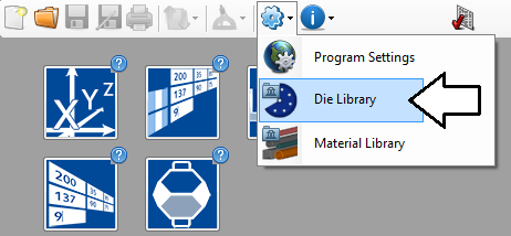
First, the die needs to be given some minimum distances. Go up to the main menu bar and click the Settings menu. Select the die library option from the drop down menu.
Step 2
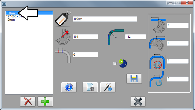
In the die library, click on the 100mm die in the die list to the left to select it.
Step 3
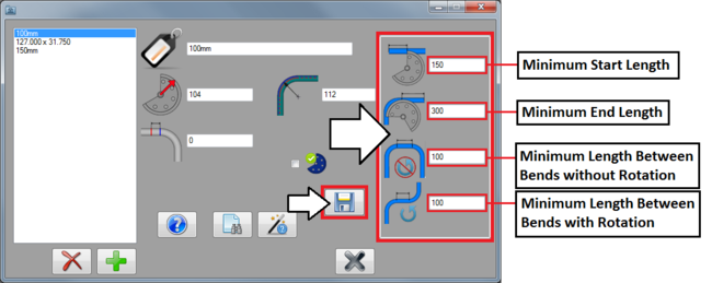
The die limitations/minimum distances are on the far right side of the window, as shown in the image below. The shortest amount of straight material allowed before, after, and between bends with and without rotations can be specified. Keep in mind that these measurements only include the straight/unbent material before and between the bends.
Enter 150 for the minimum start length, 300 for the minimum end length, 100 for the distance between bends without rotation, and 100 for the distance between bends with rotation.
Once these are all properly entered, click the save button.
Step 4
Next, a part will be created using the template designer. The part will be made with incorrect dimensions on purpose to allow the manufacture checking plug-in to detect problems in the part design.
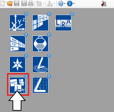
First, click the template designer button on the start up page.
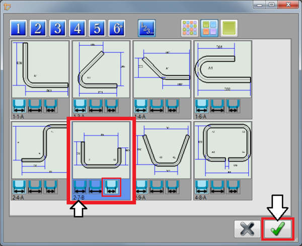
Next, a part template will be chosen from the template selection menu. First, click the show all button ![]() and then click the medium sized tile button.
and then click the medium sized tile button. ![]()
Click on the template shown below and choose inside dimensions by clicking the inside dimensions icon right below the template. Before proceeding, make sure the bottom left corner of the template says 2-7-B.
Click the green check button in the bottom right corner to finalize the template selection.
Step 5
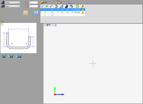
A new template part design window will open.
Step 6
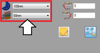
Now, select the die and material. The die and material menus are located in the upper left corner.
Choose a die by clicking the drop down menu next to the die icon. Select the 100mm die from the list, as shown in the image below. This is the die that the die limitations were given to in the first steps of this tutorial.
Choose a material by clicking the drop down menu next to the material icon. Select the 50mm material from the list, as shown in the image below. (Note: This material was made in the Material Library Tutorial. If this material is not shown in the material selection menu, either complete the material library tutorial or just select another material that is available.)
Step 7
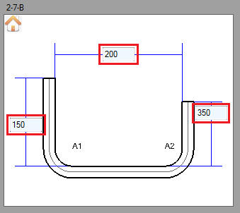
Now, the part will be designed. Enter the coordinates as shown below.
Enter 150 into the far left field, enter 200 into the upper middle field, and enter 350 into the right field. See image below.
Step 8
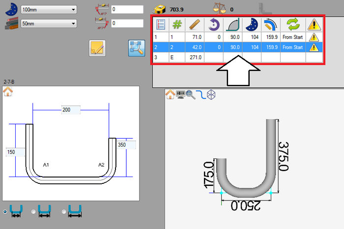
Next, look at the results table at the top of the window. In the last column, each row will have a warning icon.
Step 9
Click on one of these warning icons. This will open a window that will contain a chart of each error in the part design. There should be three different problems listed here: too short at start, too short at end, and too short between bends. In the last column, notice how the first two errors have auto-fixes available.
Step 10
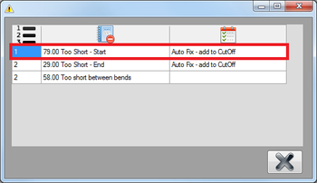
The first issue with the part design is the length of the first straight/distance before the first bend. The problem description states that the starting length is 79 units too short.
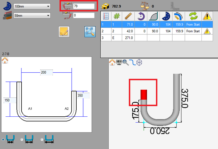
Right now, there is only 71 mm of straight length before the first bend. Adding 79 to this length will meet the minimum requirements. (In step 3, the minimum length allowed at the beginning of the part was set to 150.)
(Note: The results table may not look the same as the one pictured below. This is not necessary, but the results table output format can be adjusted in the global settings menu. Length of straight was used in this tutorial.)
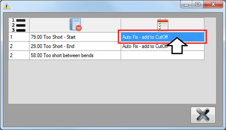
This will be fixed using the auto fix which will add the 79 mm of material to the start cut-off. Double click on the auto fix cell as shown below.
Once this is done, the error will be removed from the chart and 79 mm will be added to the starting cut-off (Left of the results table). Adding the cut-off to the starting end of the part will cause the length before the first bend to meet the 150 mm requirement.
Step 11
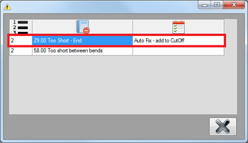
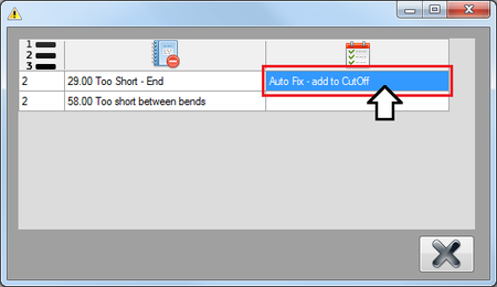
Next, the length of the last length/distance after the last bend is too short. The problem description states that the end is 29 units too short.
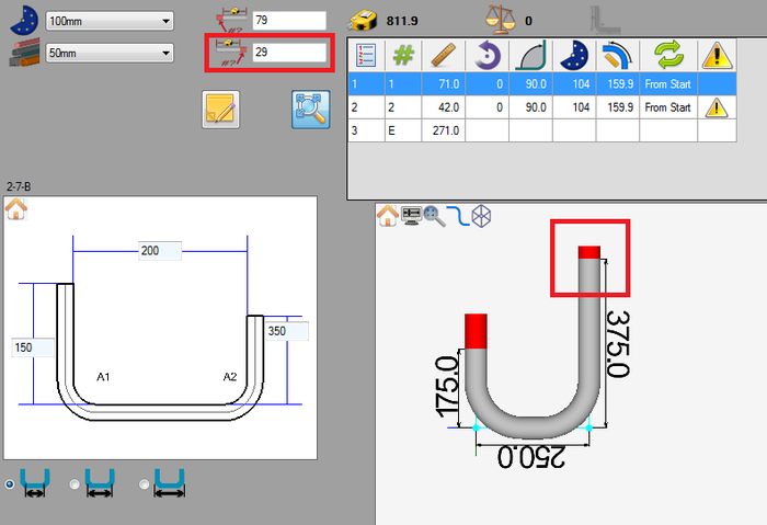
Right now, there is only 271 mm of straight material at the end of the part. Adding 29 to the end will meet the minimum requirement. (In step 3, the minimum length allowed at the end of the part was set to 300.)
This will be fixed using the auto fix which will add the 29 mm of material to the end cut-off. Double click on the auto fix cell as shown below.
Once this is done, the error will be removed from the chart and 29 mm will be added to the end cut-off (Left of the results table). Adding the cut-off to the starting end of the part will cause the last length to meet the 300 mm requirement.
Step 12
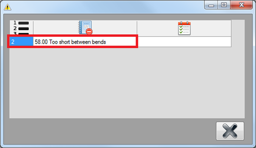
The last problem with the part doesn't have an auto-fix available, so it must be corrected by manually adjusting the part design. The error states that the part is 58 mm too short between bends.
Right now, there is only 42 mm of straight material between the two bends. Adding 58 to this length would meet the minimum requirement. (In step 3, the minimum length allowed between bends without rotation was set to 100.)
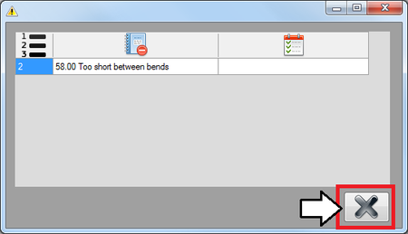
Close the error chart using the exit button in the lower right corner.
In the entry fields, change the upper middle field to 300. This will exceed the amount of material required between the bends. Instead of adding just the 58 mm, 100 mm was added to the length.
Step 13
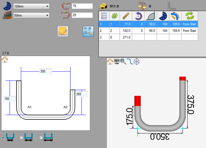
Now the part is complete and the design meets all the specified requirements. The results table should no longer display any warning icons.
Step 14
The tutorial is complete!
For further information, see the Manufacture Checking plug-in page.
