Difference between revisions of "Linear Dynamic Designer Tutorial"
| Line 1: | Line 1: | ||
==Introduction== | ==Introduction== | ||
| − | [[File:|right]]This tutorial will step through the process of designing a part (Shown to the right) in the [[Linear Dynamic Designer|linear dynamic part designer]] interface. | + | [[File:lindtut7.png|right|500px]]This tutorial will step through the process of designing a part (Shown to the right) in the [[Linear Dynamic Designer|linear dynamic part designer]] interface. |
| Line 8: | Line 8: | ||
'''''Note:''''' ''This tutorial will use millimeters as the measurement units.'' | '''''Note:''''' ''This tutorial will use millimeters as the measurement units.'' | ||
| + | |||
| + | |||
| + | |||
| + | |||
| + | |||
| + | |||
| + | |||
| + | |||
| + | |||
| Line 59: | Line 68: | ||
==='''Step 4'''=== | ==='''Step 4'''=== | ||
In the linear dynamic designer, the '''option to change the dimensions type/location is available'''. Dimensions can be measured up to the apex of the bend or just the straight lengths of tube. For more information see the [[Linear Dynamic Designer Quick Start|dimension types]] section on the linear dynamic designer quick start page. | In the linear dynamic designer, the '''option to change the dimensions type/location is available'''. Dimensions can be measured up to the apex of the bend or just the straight lengths of tube. For more information see the [[Linear Dynamic Designer Quick Start|dimension types]] section on the linear dynamic designer quick start page. | ||
| + | |||
In this tutorial, the '''length of straight''' dimension type will be used. '''Click the length of straight button''' as shown below. | In this tutorial, the '''length of straight''' dimension type will be used. '''Click the length of straight button''' as shown below. | ||
| − | [[File:]] | + | [[File:lindtut6.png]] |
| + | |||
| + | |||
| Line 68: | Line 80: | ||
==='''Step 5'''=== | ==='''Step 5'''=== | ||
| + | Now, the first length of the part will be designed. In the graphical display, a short piece of tube is already drawn out when the designer is opened. At the end of this length of tube, there will be a '''blue ring''' that will be used to adjust the length by pulling the tube to size. | ||
| + | |||
| + | |||
| + | First, '''click on the blue ring to select it'''. Once selected, it will be a darker blue as shown below. | ||
| + | |||
| + | [[File:lindtut8.png|600px]] | ||
| + | |||
| + | |||
| + | |||
| + | '''Click and drag the length to about 350 mm'''. To tell how long the length is, watch the length field on the left. | ||
| + | |||
| + | |||
| + | '''''Tip:''''' While clicking and dragging the part to size is convenient, getting exact measurements can be tricky. Any of these other methods can be used to adjust the part design: | ||
| + | |||
| + | '''''1.''''' Click on the appropriate design tool/ring and directly enter the value (length, rotation, or angle) using the keyboard. | ||
| + | |||
| + | '''''2.''''' Enter the exact length, rotation, or angle into the entry fields on the left. | ||
| + | |||
| + | |||
| + | [[File:lindtut9.png|800px]] | ||
| + | |||
| + | |||
| + | |||
| + | |||
| + | |||
| + | |||
| + | ==='''Step 6'''=== | ||
| + | [[File:lindtut10.png|right|450px]]Now the first bend will be added to the part. First, '''click the add bend button'''. [[File:addbend.png]] | ||
| + | |||
| + | The add bend button is located near the upper left corner, as shown in the image to the right. | ||
| + | |||
| + | |||
| + | |||
| + | |||
| + | |||
| + | |||
| + | |||
| + | |||
| + | |||
| + | |||
| + | |||
| + | |||
| + | |||
| + | |||
| + | |||
| + | |||
| + | |||
| + | '''After a bend is added''', another length will automatically be added to the part in the graphical display and a rotation, angle, and a new length field will appear in the entry fields area. | ||
| + | |||
| + | [[File:lindtut11.png|600px]] | ||
| + | |||
| + | |||
| + | First, the '''angle''' of this bend will be adjusted. '''Click and drag the pink ring to approximately 90°'''. ('''''Alternatives:''''' ''Type the value ('''90''') into the angle field '''or''' click the design tool/pink angle ring and directly type in the angle.'') | ||
| + | |||
| + | [[File:lindtut12.png]] | ||
| + | |||
| + | |||
| + | Next, the '''length''' after the bend will be adjusted. '''Click and drag the blue ring at the end of the part to roughly 543 mm'''. ('''''Alternatives:''''' Type the length ('''543''') into the length field or click the design tool/blue ring and directly type in the length.) | ||
| + | |||
| + | [[File:lindtut13.png]] | ||
| + | |||
| + | |||
| + | |||
| + | |||
| + | |||
| + | |||
| + | ==='''Step 7'''=== | ||
Revision as of 13:56, 3 July 2013
Contents
Introduction
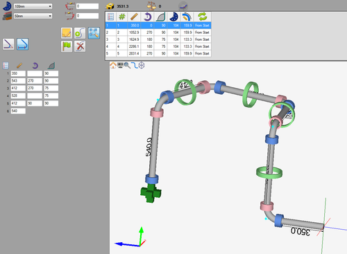
This tutorial will step through the process of designing a part (Shown to the right) in the linear dynamic part designer interface.
While designing a part in the linear dynamic designer, the die and material are chosen then the part is designed by dragging/pulling the part to size using the part designer tools and/or entering values into the entry fields.
Note: This tutorial will use millimeters as the measurement units.
Tutorial
Step 1
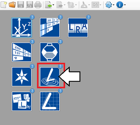
First, a new linear dynamic design needs to be started. On the start up page, click the linear dynamic designer button. 
Note: Depending on the version of software currently in use, fewer designer buttons may be included on the start up page.
Step 2
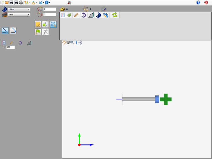
Now a new linear dynamic part designer window will open. This is where the part will be designed.
Step 3
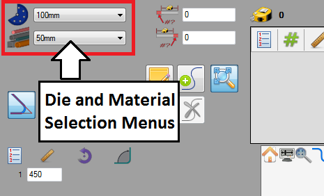
First of all, the die and material need to to be chosen. The die and material menus are located in the upper left corner of the designer window.
Choose a die by clicking the drop down menu next to the die icon. Select the 100mm die from the list, as shown in the image below. (Note: This die was made in the Die Library Tutorial. If this die is not shown in the die selection menu, please complete the die library tutorial before proceeding.)
Choose a material by clicking the drop down menu next to the material icon. Select the 50mm material from the list, as shown in the image below. (Note: This material was made in the Material Library Tutorial. If this material is not shown in the material selection menu, please complete the material library tutorial before proceeding.)
Step 4
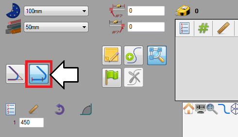
In the linear dynamic designer, the option to change the dimensions type/location is available. Dimensions can be measured up to the apex of the bend or just the straight lengths of tube. For more information see the dimension types section on the linear dynamic designer quick start page.
In this tutorial, the length of straight dimension type will be used. Click the length of straight button as shown below.
Step 5
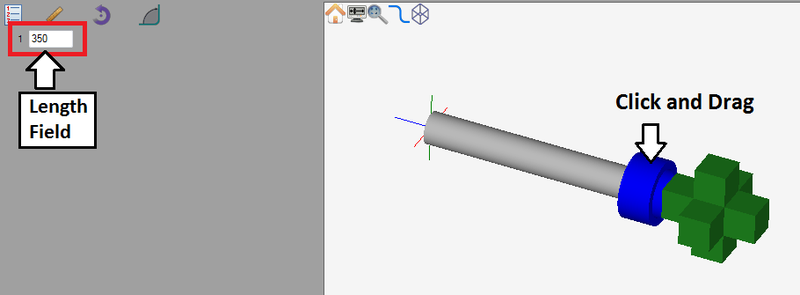
Now, the first length of the part will be designed. In the graphical display, a short piece of tube is already drawn out when the designer is opened. At the end of this length of tube, there will be a blue ring that will be used to adjust the length by pulling the tube to size.
First, click on the blue ring to select it. Once selected, it will be a darker blue as shown below.
Click and drag the length to about 350 mm. To tell how long the length is, watch the length field on the left.
Tip: While clicking and dragging the part to size is convenient, getting exact measurements can be tricky. Any of these other methods can be used to adjust the part design:
1. Click on the appropriate design tool/ring and directly enter the value (length, rotation, or angle) using the keyboard.
2. Enter the exact length, rotation, or angle into the entry fields on the left.
Step 6
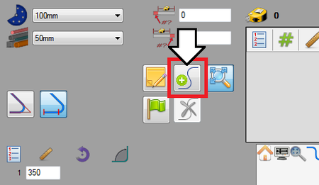
Now the first bend will be added to the part. First, click the add bend button.The add bend button is located near the upper left corner, as shown in the image to the right.
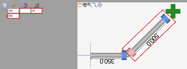
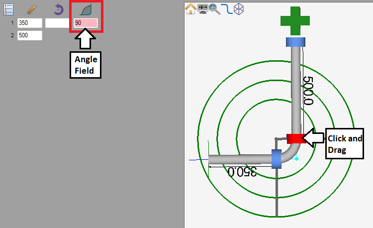
After a bend is added, another length will automatically be added to the part in the graphical display and a rotation, angle, and a new length field will appear in the entry fields area.
First, the angle of this bend will be adjusted. Click and drag the pink ring to approximately 90°. (Alternatives: Type the value (90) into the angle field or click the design tool/pink angle ring and directly type in the angle.)
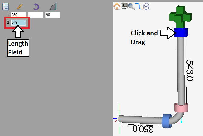
Next, the length after the bend will be adjusted. Click and drag the blue ring at the end of the part to roughly 543 mm. (Alternatives: Type the length (543) into the length field or click the design tool/blue ring and directly type in the length.)
